the Creative Commons Attribution 4.0 License.
the Creative Commons Attribution 4.0 License.
 | 04 Sep 2024
Dauphiné twin in a deformed quartz: characterization by electron channelling contrast imaging and large-angle convergent-beam diffraction
Nobuyoshi Miyajima
Danielle Silva Souza
Florian Heidelbach
A Dauphiné twin (DT) in a deformed quartz was visualized for the first time by using orientation-optimized electron channelling contrast imaging (ooECCI) under Bragg conditions of the rhombohedral planes. The visualization in backscattered electron (BSE) imaging with a scanning electron microscope (SEM) is possible due to the electron excitations of positive and negative rhombohedral planes from respective twin domains. Those diffraction planes have different structure factors and scattering amplitudes in electron diffraction and are exchanged in a pair of DT domains. The large-angle convergent beam diffraction (LACBED) patterns on the zone axis were displayed with the absence of two-fold symmetry axis along the [0001] direction in an individual twin domain but with a 180° rotation relation along the c direction between a pair of the twin domains. Related to the DT law, the LACBED pattern across a DT boundary showed the higher six-fold rotation symmetry, which is the same as that of the high-temperature β quartz. The off-axis LACBED patterns displaying Bragg lines demonstrated no angular misfit over the twin boundary. This non-orientation misfit on the twin domains allows us to confirm the visualization mechanism of DT in ECCI. The different contrast of a pair of DT domains in the BSE images originates not from a misorientation between the two domains but from different diffraction intensities between positive and negative rhombohedral planes in quartz. The observation procedure from ECCI with SEM to LACBED with TEM (transmission electron microscope) imaging presented here is indispensable for a deep understanding of the role of twinning, ranging spatially from the micrometre scale for a SEM of the bulk specimen to the nanometre scale for a TEM of the interaction with crystal defects in deformation because of their optical invisibility in a conventional petrological microscopy. Following this procedure, dislocations on a rhombohedral plane were characterized in the vicinity of DTs in naturally deformed quartz. This result implies that non-basal slips, e.g. a rhombohedral slip system, i.e. () and (), were activated in the vicinity of DTs. The activity of dislocations on a non-basal plane resulted from the interaction between DTs and dislocations during plastic deformation.
- Article
(11850 KB) - Full-text XML
-
Supplement
(5950 KB) - BibTeX
- EndNote


Dauphiné twins (DTs) in quartz can be associated with the α–β structure transition at 573 °C (Le Chatelier, 1889) but can also occur at lower temperature under high-stress conditions during deformation (e.g. Menegon et al., 2008, 2011; Trepmann et al., 2005; Trepmann and Spray, 2006; Wenk et al., 2019) and local stress in crystal growth with some impurities, e.g. titanium (e.g. Cocuzzi and Laughner, 1989; Andreas Audétat, personal communication, 2021). The twins are invisible without chemical etching on the surface in conventional polarized light optical microscopy (Fig. 1). Since 2000, the developments of electron backscatter diffraction (EBSD) techniques in field emission scanning microscopy have facilitated the analysis of the twin distributions based on the symmetry operation, a 180° rotation around the c axis (Heidelbach et al., 2000; Lloyd, 2000; Wenk et al., 2009). In metamorphic rocks, e.g. quartzite, the twins have been investigated in relation to fabric transitions from the basal to non-basal rhombohedral slip systems (Menegon et al., 2011). Menegon et al. (2011) explained that the presence of Dauphiné twins plays an important role in the distribution of the intracrystalline plastic deformation in quartz, as well as in the activation of different sets of slip systems, i.e. rhombohedral slip systems. The identification of the activities of rhombohedral slip systems, especially a slip that occurred on either positive or negative rhombohedral planes because of a switch relative to each other by a Dauphiné twin, is indispensable for understanding the role of the twinning in deformation (Lloyd et al., 2004; Pehl and Wenk, 2005; Rahl et al., 2018; Wenk et al., 2019). The authors in the previous studies imply the importance of dislocation activity on the twinning process as such but also that twins can affect the glide of dislocations and maybe even that twin boundary migration might play a role during deformation.
The direct identification of Dauphiné twins by EBSD is very common, whereas the direct identification of Dauphiné twins in deformed quartz is very rare in the literature involving transmission electron microscopy (e.g. Gratz et al., 1988; Goltrant et al., 1991; Cordier and Doukhan, 1995; Jacob and Cordier, 2010) because of technical and intrinsic difficulties in demonstrating the symmetry operation in conventional electron diffraction techniques (i.e. selected area electron diffraction (SAED) with dynamical diffraction effects). The difficulty of detecting a Dauphiné twin in deformed quartz is due to the high density of dislocations forming subgrain boundaries which cause an orientation misfit in the vicinity of the twin boundary (e.g. Barber and Wenk, 1991). The orientation misfit across a subgrain boundary (e.g. less than 1–2°; Fig. 10) prevents the evaluation of the character of a DT in electron diffraction and diffraction contrast imaging with a transmission electron microscope (TEM) based on the differences in structure factors and scattering amplitudes of positive (e.g. 301) and negative (031) rhombohedral planes, which can be exchanged by a 180° rotation around the c axis in a DT. To overcome this difficulty, Hamers et al. (2017) applied cathodoluminescence imaging to a scanning electron microscope to assist the visualization of Dauphiné twin boundaries for a TEM.
In this study, we have intended to visualize for the first time a pair of DT domains having different backscattered electron (BSE) contrasts by using orientation-optimized electron channelling contrast imaging (ooECCI; Miyajima et al., 2018, 2019) in a field emission scanning electron microscope. The mechanisms of the visualization in the ooECCI are clarified by means of a combination of the TEM characterizations with a focus ion beam (FIB) micro-sampling. The large-angle convergent beam electron diffraction (LACBED) patterns from adjacent twin domains and an area across the boundary are used to identify their symmetry relations and non-misorientation across the twin boundary. In relation to the transitions from the basal to non-basal rhombohedral slip systems in a pervasively twinned quartz (Menegon et al., 2011), an associated dislocation in the vicinity of DT boundaries is also examined to identify the Burgers vector of an individual dislocation using the thickness contour fringe method in weak-beam dark-field TEM (TEM-DF) images (Ishida et al., 1990; Miyajima and Walte, 2009). Our aims are (1) to demonstrate the visualization of the twins in ooECCI for the first time, (2) to explain the mechanisms by using site-specific TEM sampling analyses, and (3) to offer a new approach combining TEM with ECCI to understand the role of Dauphiné twinning during deformation in quartz.
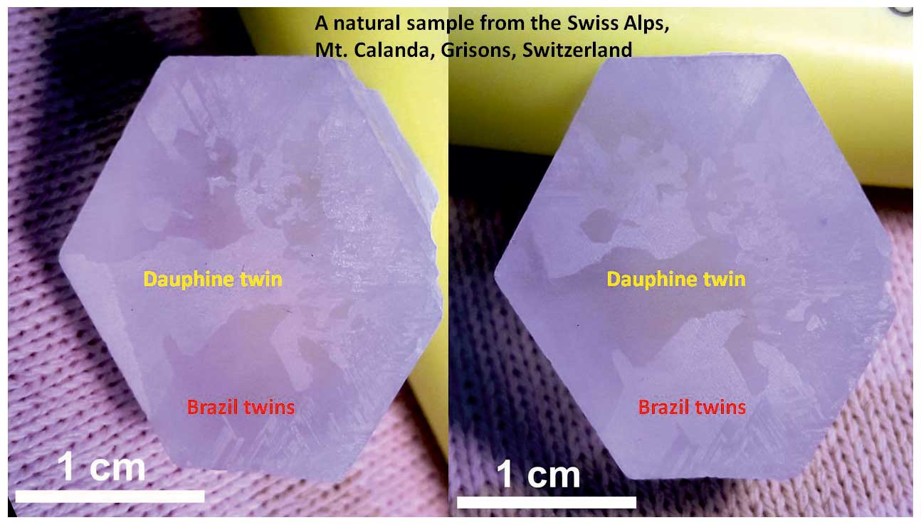
Figure 1Optical photomicrograph of a natural quartz from Calanda mountain, Grisons, Switzerland (with chemical etching on the surface, courtesy of Andreas Audetat), taken under different illumination conditions.
2.1 Sample investigated
Two thin sections of a quartz porphyroclast (hereafter referred as quartzite) in a granitoid protomylonite from the Austroalpine Arolla unit of the Dent Blanche nappe in the north-western Italian Alps (Menegon et al., 2008, 2011) were investigated by using field emission scanning electron microscope (SEM) and TEM apparatuses at the Bayerisches Geoinstitut (BGI), University of Bayreuth. In the granitoid protomylonite sample, quartz shows a clear shape-preferred orientation subparallel to the foliation and includes about 5 % volume of recrystallized grains. The mineral assemblage is quartz–albite–chlorite–epidote–muscovite–actinolite–stilpnomelane, formed under greenschist facies at 300–400 °C and fluid-present conditions (Menegon et al., 2011). The temperature is below the α–β transition in quartz, where DTs are usually not nucleated. However, in the protomylonite studied, mechanical DT developed pervasively during the incipient stage of deformation within two porphyroclasts. The quartz grains are oriented with a negative rhombohedral plane almost orthogonal to the compression direction (Menegon et al., 2011). One of the thick sections of the porphyroclast 300 µm in thickness (Supplement Fig. S1) was polished by using a 0.25–1 µm diamond paste followed by a 40 nm silica colloidal suspension for ECCI SEM analyses. Dashed rectangles encompass quartz grains where Dauphiné twins were evident in the previous study (Menegon et al., 2011). Greenish portions in the rock (Fig. S1) mainly consist of actinolite, chlorite, and altered albite.
2.2 Orientation-optimized ECCI with a SEM
Orientation-optimized ECCI (ooECCI) was performed with a field emission scanning electron microscope (FE-SEM; Leo Gemini 1530, Zeiss) equipped with an annular-scintillator-type backscattered electron detector (CENTAURUS of KE Developments) and an EBSD system (Nordlys II of Oxford Instruments), operating at 20 kV acceleration voltage. High-intensity Kikuchi bands of the rhombohedral planes in quartz grains were excited under the Bragg conditions by judging the EBSD patterns obtained. For the ECCI, the further orientation alignment to excite the Kikuchi band was performed by using a conventional single-axis tilt- and rotation-stage system. After orientation determinations by using EBSD patterns of the target quartz, more precise orientation optimization was performed in monitoring BSE contrast on a series of BSE images by changing the tilt angle by 0.5 to 1.0° steps (e.g. Fig. 9 in Miyajima et al., 2018). After the fine orientation optimization, BSE images under the excitation of rhombohedral bands were recorded at a slow scan rate, e.g. 4.5 min per frame in a line-average mode. The detailed procedure of ooECCI for minerals is described in Miyajima et al. (2018).
2.3 FIB micro-sampling and Ar milling for TEM specimen preparation
After the ECCI observation, four selected areas for further TEM analysis were micro-sampled by using a dual-beam FIB machine (Thermo Fisher Scios DualBeam) at BGI. The conditions of the Ga ion beam for the milling were at 30 kV and probe currents were reduced from 30 nA for the trench milling to 300 pA for the thinning of the TEM lamella; the TEM lamella was finally cleaned at 5 kV and 48 pA. The dimension of the TEM lamellae was changed from µm for trench milling to 2 µm thickness for an extracted lamella at first and then finally polished to 20 µm width, 10 µm depth, and about 150 nm thickness for the final thinning. The detailed procedure for a FIB sample preparation is described in Miyajima et al. (2019). To investigate an intracrystalline interaction of DT boundaries and dislocation subgrain boundaries in the quartzite, a few TEM specimens were also prepared by conventional Ar ion milling (Gatan Model 600 DuoMill).
2.4 TEM-DF, precession SAED, and LACBED
The Dauphiné twin boundary was identified by using conventional dark-field imaging with 1 (a rhombohedral plane). Dark-field TEM imaging was performed at 200 kV acceleration voltage in a field emission scanning transmission electron microscope (FEI Titan G2 80-200 S/TEM) at BGI. To determine the symmetry operation of the twin, the LACBED patterns across the boundary with respective twin domains were obtained in a conventional TEM mode, assisted with a beam precession mode by using the deflection coils in the same TEM system. Using the beam precession mode combined with a deflection coil to tilt the direct beam back to the optical centre, precession selected electron diffraction was carried out with the maximum precession semi-angle of about 3°.
3.1 Visualization of Dauphiné twin boundary (DTB) in orientation-optimized ECCI with an FE-SEM
BSE imaging of the quartzite specimens with an FE-SEM displayed black- and white-contrast domains separated by irregularly shaped boundaries (Figs. 2a and S2), which are likely to be DTs. In EBSD measurements of a pair of those domains, the corresponding Kikuchi patterns indicate the differences in diffraction structure factors and scattering amplitudes from positive and negative rhombohedral planes of the quartz structure (Figs. 3 and S3). The sample orientation was aligned by the tilt and rotation system of the SEM to excite the Kikuchi band under the Bragg condition with 1 or Kikuchi line (KL) corresponding to the (031) plane, denoted as KL(031) hereafter, which gave the best BSE contrast on a perfect visualization of a pair of DTBs (Fig. 2b). We optimized the BSE imaging conditions; especially we used a probe current of less than 9 nA, which is controlled by the diameter of the probe-forming aperture between 60 and 120 µm in our FE-SEM system because the probe current at 20 kV acceleration voltage was on the threshold to prevent any beam irradiation damage (i.e. amorphization) on the quartz crystal structure.
In the ECCI image of the DT boundary (Fig. 2b), which was recorded after the above-mentioned orientation optimization to a Bragg condition, i.e. an ooECCI image, the DT interfaces are more straight than those of the subgrain boundaries consisting of an array of dislocations. This DT interface indicates no noticeable interactions with active dislocations at present after the deformation process in nature. Furthermore, no orientation misfit across the twin boundary was detected in the EBSD analysis, and this was also confirmed with the further LACBED analyses with a TEM, described in Sect. 3.2. It is noteworthy that the deformed quartz grains often have a high density of dislocations and subgrain boundaries. Those defects complicate the visualization of DT boundaries in bright-field (BF) and dark-field (DF) TEM imaging because the differences in diffraction intensities from different rhombohedral planes (e.g. the positive (301) and negative (031) planes) in the electron diffraction cannot contribute properly to those TEM images due to the high density of misoriented boundaries and subgrains generated by such dislocation activity.
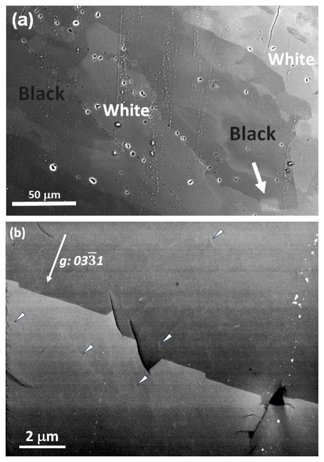
Figure 2(a) BSE image of a DT boundary at low magnification. (b) At high magnification, the ECCI image was recorded under a Bragg condition. The area is indicated by the white arrowhead and a trace of hydrocarbon contamination in the image (a). The line contrasts of dislocations indicated by triangle arrowhead are also visible in (b).
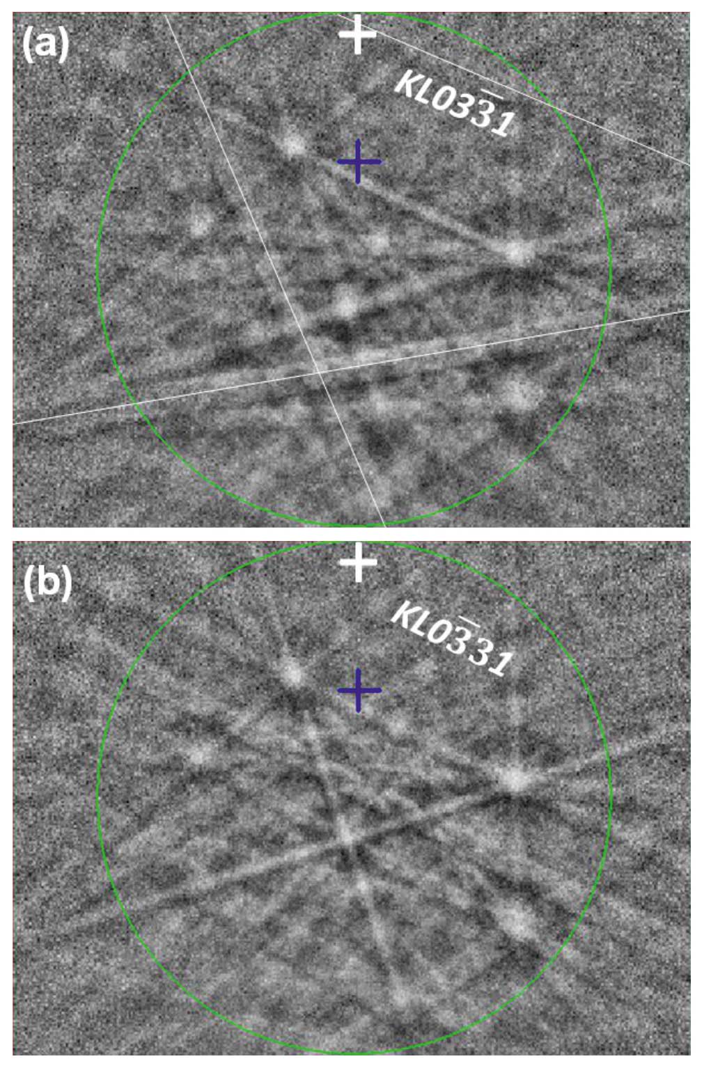
Figure 3EBSD patterns to show Kikuchi bands from a pair of rhombohedral planes. The Kikuchi patterns were obtained from (a) black-contrast domain, upper part in Fig. 2b, and (b) white-contrast domain, lower part in Fig. 2b. The Kikuchi line (KL) of the (031) plane (negative steep rhombohedra) is visible in the black domain (a), while the KL of the (031) plane (positive steep rhombohedra) is not visible in the Kikuchi pattern of the white domain (b). The white cross and blue cross indicate the sample normal position and pattern centre, respectively. The band of KL (031) is on the sample normal position; the (031) plane was excited in the ooECCI in Fig. 2b. The three arbitrary Kikuchi bands indicated by the thin white lines (eye guides to indicate the positions of the bands in comparison) have larger differences in intensity of the bands between the two EBSD patterns.
3.2 Identification of DTs by using conventional dark-field images and off- and on-axis LACBED with a TEM
Figure 4 shows several TEM lamellae being prepared after the twin characterization by EBSD and ECCI with a SEM by using the site-specific FIB sampling on the target areas (Miyajima et al., 2019). Figure 5 shows typical bright-field and dark-field TEM images of a DT under two-beam conditions of the rhombohedral planes, e.g. g= 301, because those have one of the highest structure factors among the rhombohedral planes in electron diffraction at 200 kV and also a high change between the negative and positive planes (e.g. Table 2 in Jacob and Cordier, 2010). The TEM image displays a straight Dauphiné twin boundary along the [0001] direction. The pair of twin domains has different frequencies of the thickness contour fringes for domains of similar thickness, which reflects the differences in the diffraction structure factors and scattering amplitudes of negative and positive rhombohedral planes, i.e. 01 and 301 (i.e. a denser fringe pattern corresponds to a higher structure factor). Precession selected area electron diffraction patterns taken separately from the Dauphiné twin domains along the zone axis also indicate different intensities of the () and () and the (401) and (401) rhombohedral planes (Fig. S4). Those pairs of rhombohedral planes have large differences in kinematical intensities across DT boundary, as tabulated in Jacob and Cordier (2010).
The large-angle convergent-beam electron diffraction (LACBED) pattern from the DT boundary indicates no misorientation between twin domains because of the continuity of the Bragg lines (Fig. 6). Some lines are not affected by the boundary, while some lines disappear or undergo a visible change in intensity at the boundary (Cordier et al., 1995). This result supports the different ECCI contrasts (originating from the differences in the BSE intensity with the FE-SEM) on the twin domains (white or black domain) in Fig. 2 originating not from a misorientation across the twin boundary but from the differences in the structure factors and scattering amplitudes of a pair on the rhombohedral plane in electron diffraction at 20 kV for the FE-SEM.
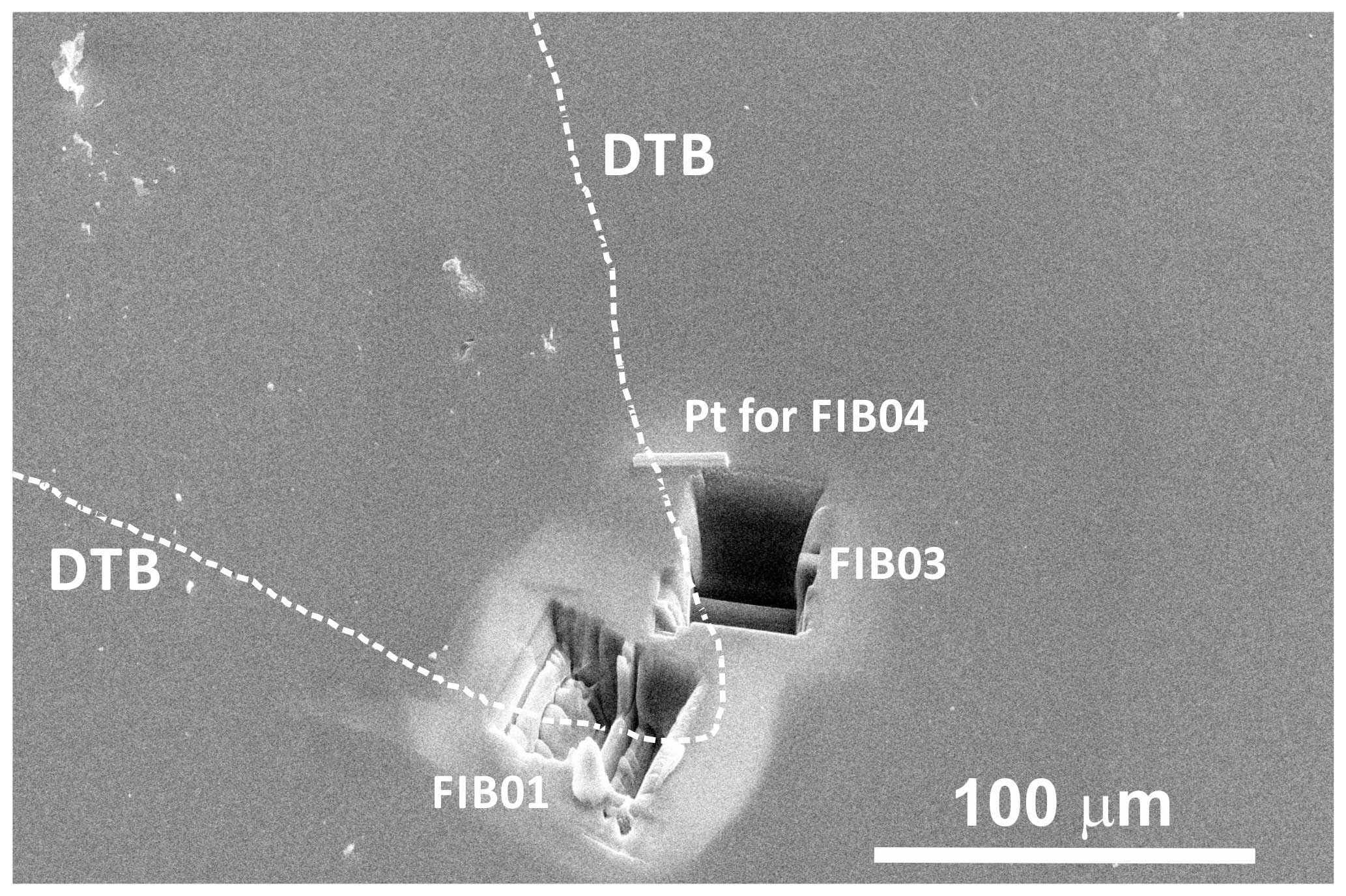
Figure 4FIB micro-sampling from areas of the DT boundary (outlined in a dashed white line) shown in the lower right of Fig. 2a. “FIB01” and “FIB03” are the trenches after the lift-out of the TEM lamellae, and “Pt for FIB04” is a platinum deposition for the FIB milling.
By identifying the symmetry operation of the Dauphiné twin in comparison to high-temperature β quartz, the three LACBED patterns of each one of the twin domains (Fig. 7a and c) and an area across the boundary (Fig. 7b) display a two-fold symmetry along the c axis in the pattern of the area across the boundary. The symmetry of each twin domain on the left and right (Fig. 7a and c) does not have a two-fold axis along the c axis (i.e. no 180° rotation around the c axis). It is noteworthy that an individual low-temperature α quartz grain does not have a two-fold symmetry along the c axis but a pair of domains in DT have a relation of the two-fold symmetry, which results in a six-fold symmetry (three- and two-fold symmetry) axis corresponding to that of high-temperature β quartz (e.g. Jacob and Cordier, 2010).
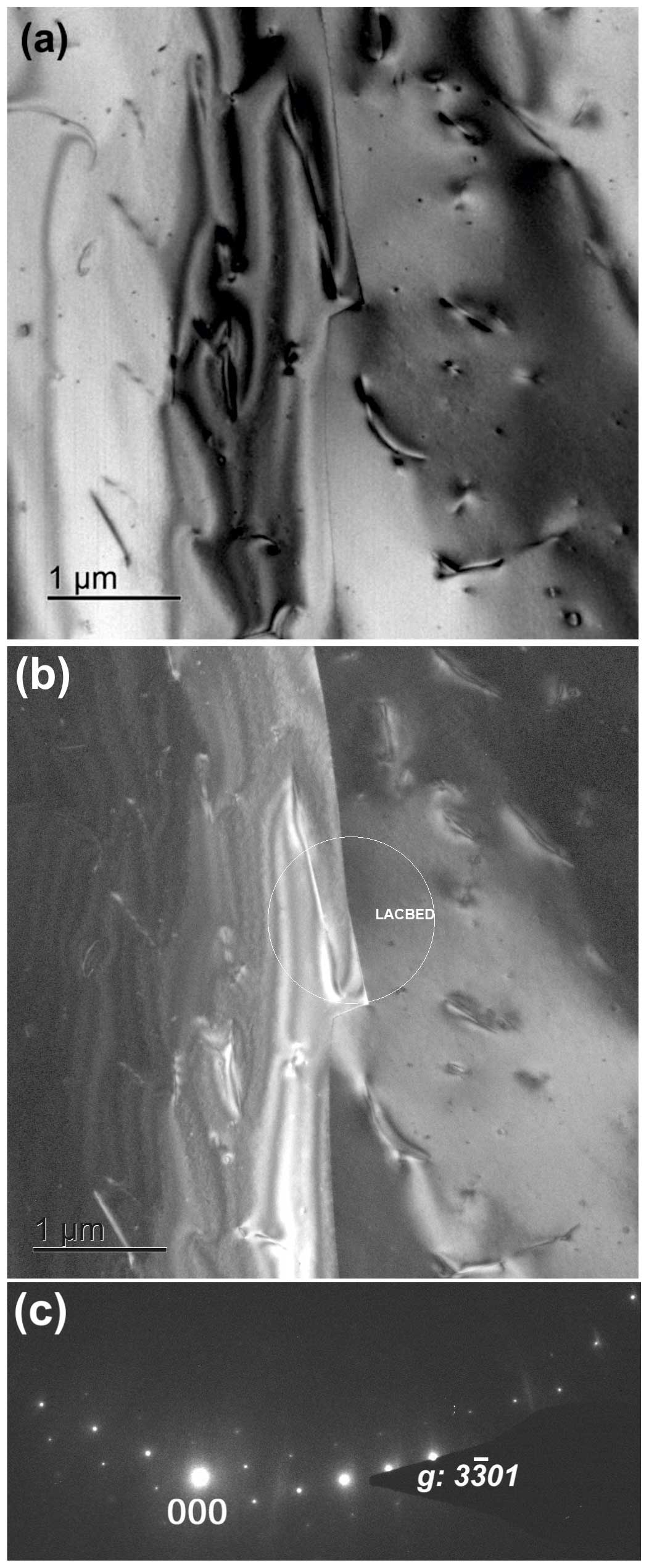
Figure 5(a) Bright and (b) dark-field TEM micrographs of a Dauphiné twin boundary (01). Several dislocations are also visible. The white circle in the (b) indicates the area of LACBED in Fig. 6. (c) The corresponding selected area electron diffraction pattern to the TEM image (b).
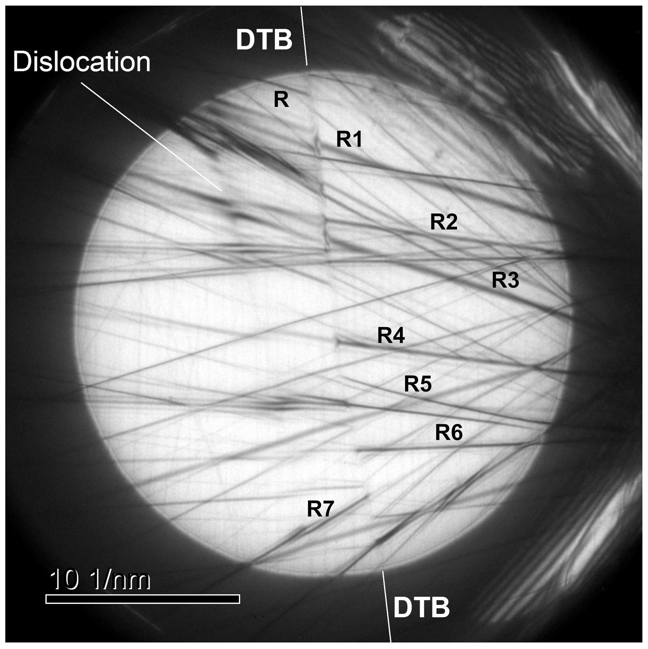
Figure 6Large-angle convergent-beam electron diffraction (LACBED) pattern showing the effect of the Dauphiné twin boundary (DTB). Some Bragg lines are not affected by the boundary, while some other lines (indicated by R) disappear or undergo a visible change in intensity at the boundary. The indices are R1(10), R2(10), R3(10), R4(013), R5(014), R6(012), and R7(01. Some splitting of lines indicates the existence of a dislocation in the vicinity of the boundary.
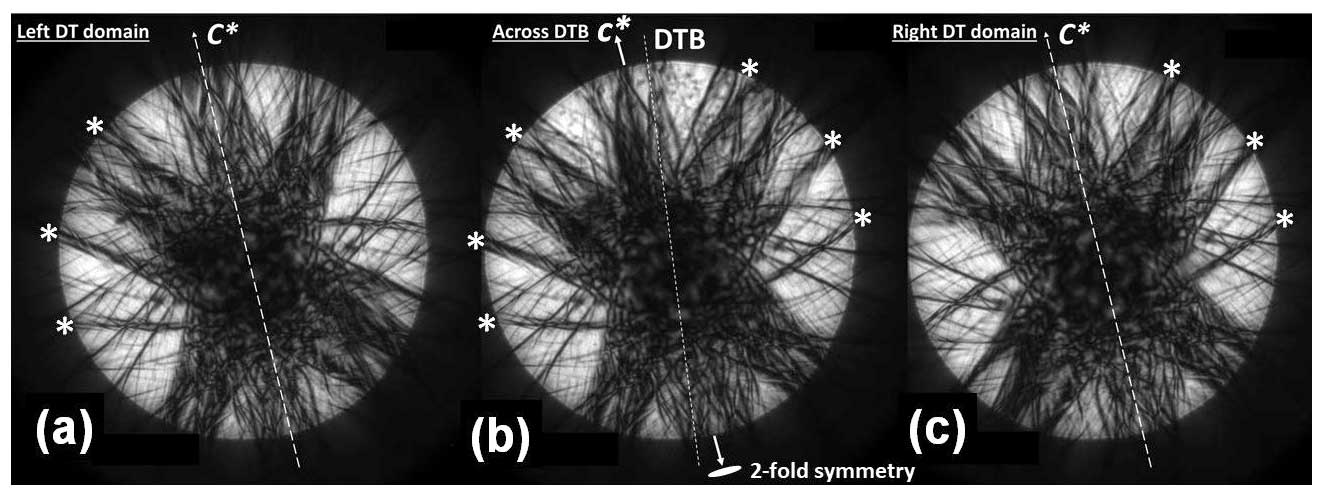
Figure 7Zone-axis LACBED patterns taken in both of the Dauphiné twin domains and across the twin boundary along the zone axis. The patterns of the Bragg lines indicate the symmetry of α quartz and its DT relations. No two-fold symmetry axis is along the c axis in both (a) left and (c) right patterns, but (b) the middle pattern across the DTB appears to have the two-fold symmetry equal to that of the high-temperature form (β quartz). The asterisk * symbol is a reference of the Bragg lines indicating a symmetry operation among the two domains and DTB.
3.3 Burgers vector analysis of dislocations in the vicinity of a DT boundary
In order to investigate possible fabric transitions from the basal to rhombohedral slip system near the DT boundary (Menegon et al., 2011), the Burgers vectors and slip planes of dislocations were investigated in weak-beam dark-field (WBDF) imaging. The results show that a high density of dislocations indicating rhombohedral slip, i.e. or , was activated in the vicinity of the DT during plastic deformation (Figs. 5 and 8). The WBDF image (Fig. 8) shows dislocations on the right-side domain of the investigated Dauphiné twin. The trace analysis of the directions of the dislocation lines on potential slip planes indicated that a higher density of dislocations is not on the (0001) basal plane but on the rhombohedral or acute rhombohedral planes.
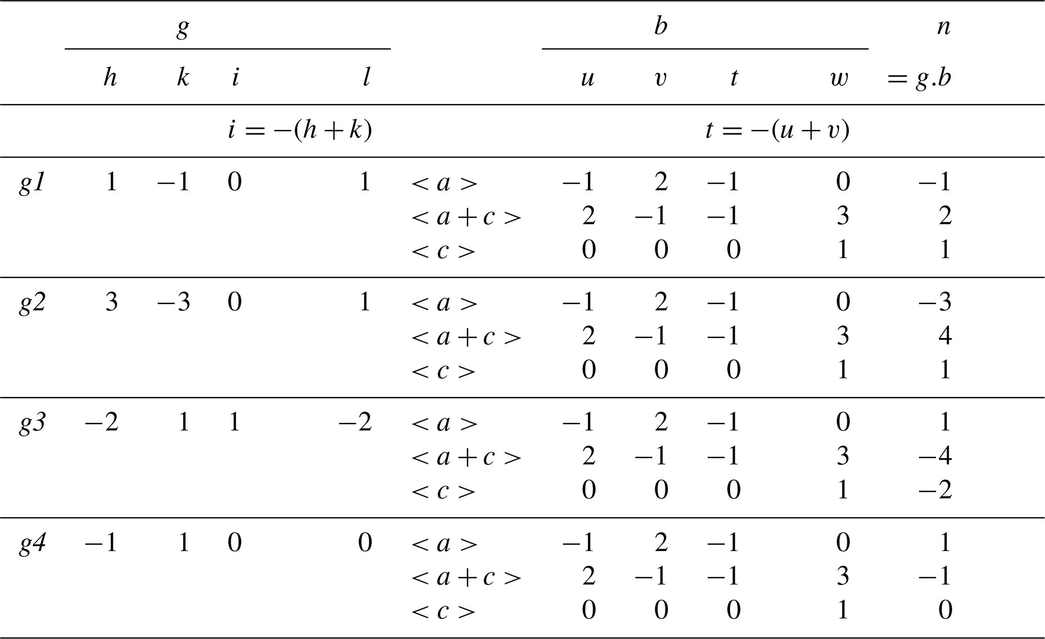
To confirm the slip system, i.e. Burgers vector <uviw> slip plane {hkil} of the dislocations in the vicinity of the DT boundaries, the Burgers vector of a dislocations was determined by using the thickness contour fringe method in WBDF imaging (Fig. 9). The diffraction conditions in the WBDF images are shown in selected area electron diffraction patterns (Fig. S5). Table 1 summarizes the result of scalar products of the possible Burgers vectors and diffraction vectors using the thickness contour fringe method (Ishida et al., 1980; Miyajima and Walte, 2009; Mussi et al., 2021) for a deformed quartz. Although some of the determined signs of vector products n are not exactly the same as the ones calculated, the results of all the magnitudes of the dot products (scalar products) in the dislocation analysis are consistent with a Burgers vector of .
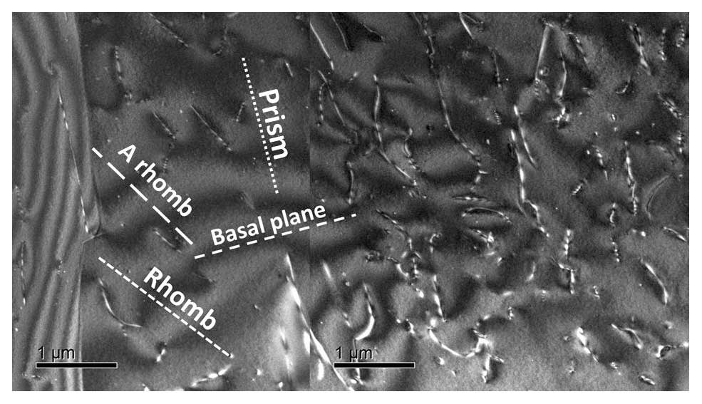
Figure 8Dark-field TEM micrograph of the right-side domain of the same Dauphiné twins (with diffraction vector, ). The electron beam in the DF image is along the zone axis. The dashed lines indicate projections and traces of potential slip planes. Basal plane (0001), rhombohedral plane (Rhomb; ), acute rhombohedral plane (A rhomb; ), and prism plane (). Note that two different TEM images are composed manually. The vertical line contrast in the centre is an artefact due to the composition. The DT boundary is located vertically at the right side.
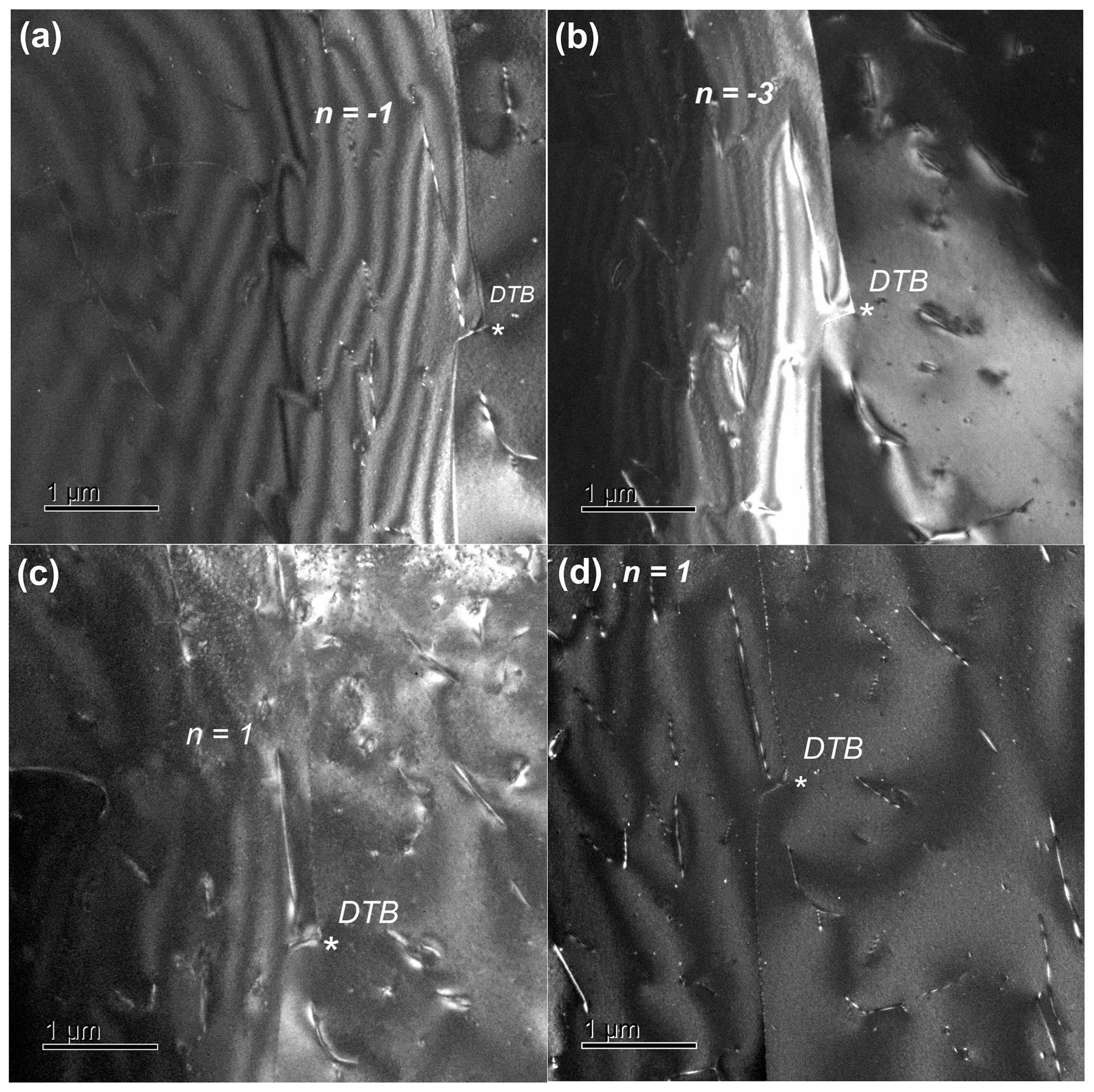
Figure 9Weak-beam dark-field TEM images of dislocations on the rhombohedral planes. Analysis of the Burgers vector of a dislocation in the vicinity of DT by using four different diffraction conditions with (a) g1 = 101, (b) g2 = 301, (c) g3 = 11, and (d) g4 = 100. The scaler product is g.b, where g the diffraction vector and b the Burgers vector are show in the Table 1.
Table 1Burgers vector analysis of a quartz in the vicinity of a Dauphiné twin boundary. The result in these four diffraction conditions is consistent with a Burgers vector of . In this case, . This number n corresponds to the g.b scalar product, where g is the diffraction vector and b the Burgers vector on the assumptions of slips along , , and .
4.1 Importance of the identification of slip on the rhombohedral plane in a twinned quartz in relation to a switch in the dominant slip systems during plastic deformation
The Dauphiné twinning exerted a control on the selection of the dominant slip system in a quartzite (Menegon et al., 2011). Therefore, the identification of a slip on the rhombohedral plane in the twinned quartz is important. To determine the slip system in a quartz grain with the TEM, the tracing of projected dislocation lines under different diffraction conditions is necessary (e.g. TEM tomography observation reported by Mussi et al., 2021). Even so, the directions of all the dislocation lines in Figs. 8, S7, and S8 are consistent with those of non-basal planes such as , {m} prism planes; , {r} rhombohedral; and , {π} acute rhombohedral planes, implying the potential slip system in the vicinity of DTs is a non-basal slip system (Fig. 10). Menegon et al. (2011) reported on the same quartzite that the acute rhombohedral slip, e.g. , is particularly important for the deformation of quartz because they confirm that the presence of DTs induced a switch in the dominant active slip systems from the basal plane to the rhombohedral plane during plastic deformation. Menegon et al. (2011) explained the mechanisms of the switch of the dominant slip systems: the negative {z} and positive {r} rhombohedral twin domains (referred to as r twin and z twin, respectively, which are defined as a pair of one positive rhombohedral plane {r} and one negative rhombohedral plane {z} normal to a maximum compressive axis) behave differently during progressive plastic deformation. The z-twin domains behave as relatively less deformable and the r-twin domains more deformable objects. As a result of the progressive lattice distortion of the r-twin domains, i.e. softer positive rhombohedral plane, original Dauphiné twin boundaries are modified to general high-angle boundaries and became a hindrance for the easy glide of dislocations along the misaligned basal plane. Basal planes and the c axes are misaligned across what was originally a discrete twin boundary. Under these conditions, other geometrically favoured slip systems are activated in the pervasively twinned regions, such as {π} and . Therefore, each twin domain experiences a different microstructural evolution. In Sect. 4.2, the evolution is visualized in TEM images with a difficulty in the identification of a Dauphiné twin boundary in a deformed quartzite. In this study we have consistently found a rhombohedral or acute rhombohedral slip, , or in the vicinity of a DT boundary.
In addition, Wenk et al. (2019) described the difficulty that the positive and negative rhombohedral planes are exchanged by twinning (illustrated in Fig. 10). The poles of equivalent-unit rhombohedral planes are more or less at right angles (e.g. among the (r1), (r2), and (r3) planes in Fig. 10). If one pole of a rhombohedral plane (the (r1) of the right quartz in Fig. 10) is parallel to the compression direction (Z) during deformation, there are the other two poles of the rhombohedral planes (the (r2) and (r3) in Fig. 10) that are perpendicular to it (the (r1) in Fig. 10; e.g. Fig. 2b in Menegon et al., 2011). The relation makes fabric analyses by using EBSD and deformation difficult because of the fact that alignment of one positive rhombohedral plane forces the other two into a situation with practically zero resolved shear stress (because of the almost 90° distance). In this context, they cautioned that a pole figure for positive rhombohedral planes shows a maximum perpendicular to the foliation, whereas negative rhombohedral planes generally display a minimum in that position. It is a problem to distinguish which rhombohedral planes (i.e. positive or negative rhombohedral planes) are really concentrated in the direction perpendicular to the foliation on the presence of DTs in deformed quartzite because {r} and {z} are exchanged on the twinning. Thus, it should be approached with weak-beam dark-field TEM imaging to identify the characters of individual dislocations, Burgers vectors, and the line directions in the vicinity of DTs, ideally by distinguishing {r} from {z} or vice versa.
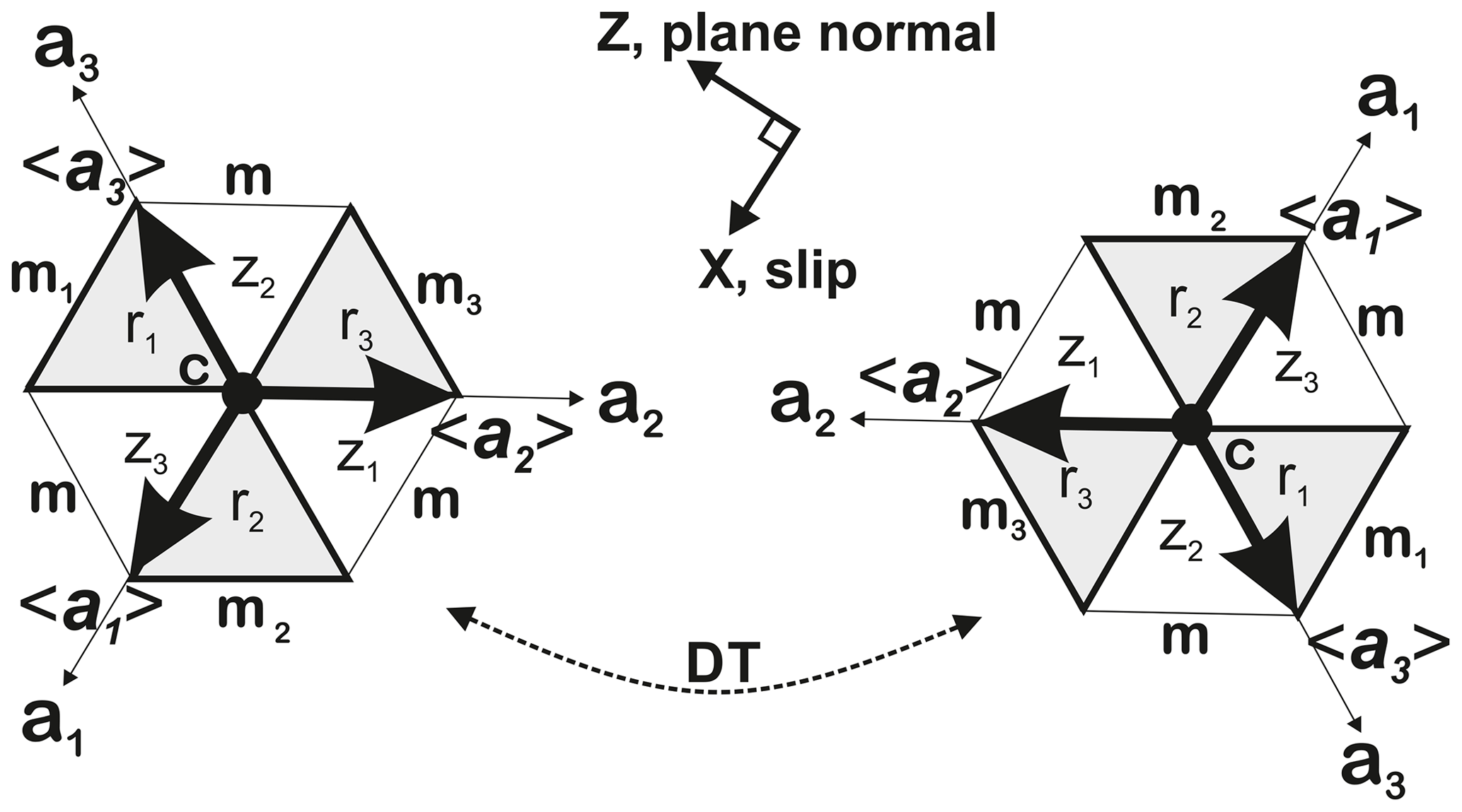
Figure 10Schematic drawing of the relations of the slip directions, prism {m}, positive {r} and negative {z} rhombohedral planes in Dauphiné twin (DT) quartz in a view of the [0001] direction. The left and right ones are in a relation rotated with 180° along the c axis. The subscript number of the plane symbols indicates a pair of a slip system, e.g. [a1](m1), [a1](r1) and [a1](z1). Positive rhombohedral planes (r1)= (011), (r2) = (101), (r3) = (101)) and negative rhombohedral planes ((z1) = (011), (z2) = (011), (z3) = (101)).
4.2 The difficulty of the identification of a Dauphiné twin boundary (DTB) in a deformed quartzite by using dark-field TEM imaging
The transformation of a Dauphiné twin boundary to a general high-angle boundary makes the identification difficult due to the loss of the pristine Dauphiné twin relation. Dark-field TEM images of a DT display the typical microtextures of a tangle of a dislocation network or subgrain boundary with a Dauphiné twin boundary (Figs. 11 and S6; in Fig. S6d we used the software of Seto and Ohtsuka, 2022). On the other hand, a weak-beam dark-field image (Figs. 12 and S7) shows an irregular shaped dislocation network in a quartz without detecting any pristine DTs in the same quartzite. In the latter case, it is likely that the accumulated lattice distortion by dislocation mobility and dislocation pileups on the boundary (Fig. S7) modified the original twin boundary to a low-angle boundary during plastic deformation (as Menegon et al., 2011, proposed). The TEM images with diffraction vectors of the rhombohedral planes exchanged by the DT rotational operation (Figs. 13 and S7) indicate the pervasive interactions between dislocations and Dauphiné twins (DTs) causing a transformation from pristine DT boundaries (Fig. 5) to low-angle boundaries during deformation of a quartz (Figs. 12, 13, and S8). The orientation misfit across the subgrain boundary makes DT boundaries difficult to see in diffraction contrast TEM imaging because the amplitude contrast based on electron scattering in electron diffraction cannot be separated from the contributions of the orientation misfit in the case of the existence of an interaction between DTB and dislocation array forming a tilt boundary (Figs. S7b and S8). It should be noted that no pristine DTB was detected in the FIB04 TEM sample (Fig. 4) with the TEM. In the FIB micro-sampling area, we detected a low-angle boundary intersected with the target DTB visible in the lower-right part of the BSE image (in Fig. 2a). This is an example of the difficulty; the interaction to form low-angle boundaries is the main reason why a direct identification of Dauphiné twins in deformed quartz are very rare in the literature involving only TEM-BF/DF imaging without pre-assisted EBSD analysis and cathodoluminescence imaging (Hamers et al., 2017). The combination of ECCI with a SEM and LACBED with a TEM in this study demonstrates the visibility of Dauphiné twins with an FE-SEM and the visualization mechanism with its difficulty due to their interactions with active dislocations in a deformed quartzite. We offer a new approach to visualize Dauphiné twins by using the ECCI imaging (Fig. 2) with an FE-SEM and to investigate an interaction of DT with dislocations in TEM-BF and TEM-DF imaging (Figs. 11, 12, and 13) assisted with a site-specific micro-sampling of TEM foils in a FIB milling machine (Miyajima et al., 2019).
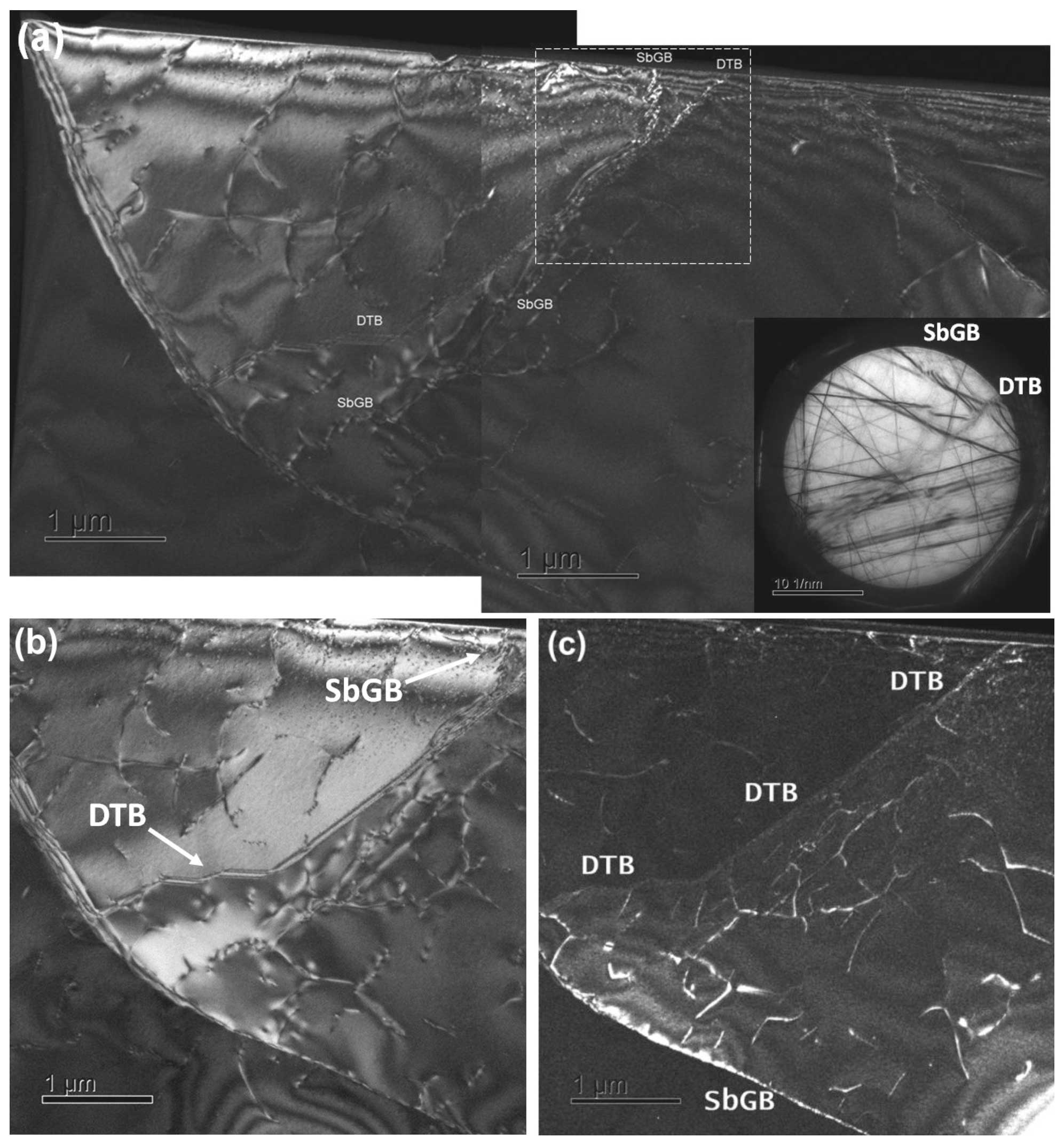
Figure 11Interaction of a dislocation subgrain boundary (SbGB) with a Dauphiné twin boundary (DTB). The electron beam is along the [21] zone axis and nearly normal to the (10) rhombohedral plane. (a) WBDF image with (the deviation error, s>0) displaying a subgrain boundary (SbGB) associated with dislocations. The lower-right inset is a LACBED pattern from the centre square area (indicated by dashed white lines). The misfits and discontinuities of the intensity of Bragg lines indicate SbGB and DTB, respectively. (b) DF image with the same diffraction vector (s=0) displaying a DTB. (c) DF image with 1 and 021 (s=0) in different domains having different structure factors in negative and positive rhombohedral planes, respectively, exchanged by a DT. The symbols DTB and SbGB indicate the positions of a DT boundary and a subgrain boundary, respectively.
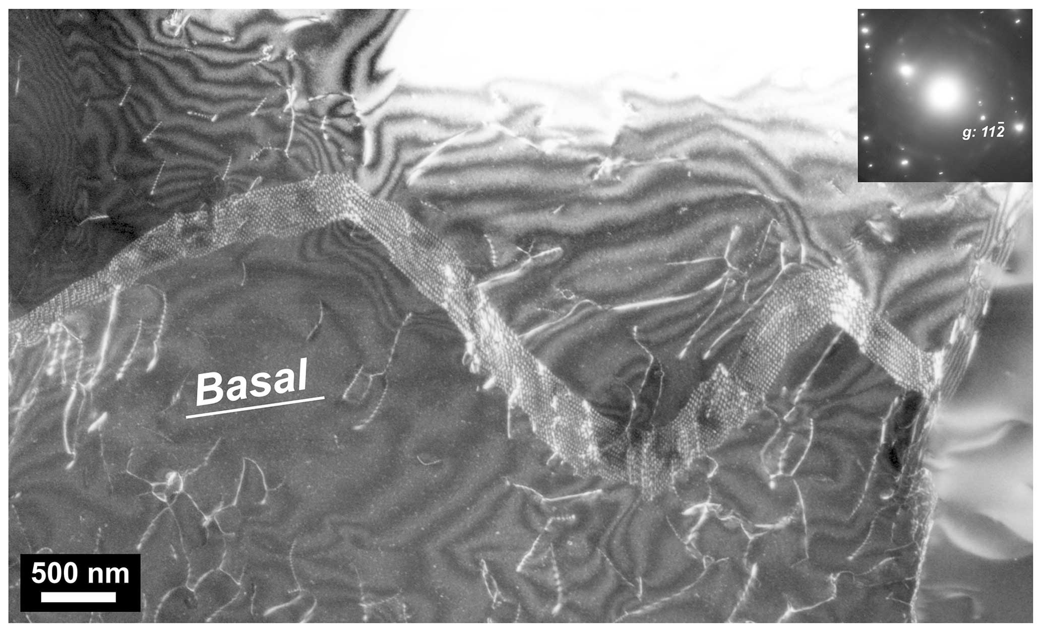
Figure 12An example of dislocation network in a quartz grain in the quartzite from the Austroalpine Arolla unit of the Dent Blanche nappe in the north-western Italian Alps. Weak-beam dark-field TEM image with . No pristine Dauphiné twins exist in the image. The trace of the basal plane of the quartz is indicated as “Basal”.
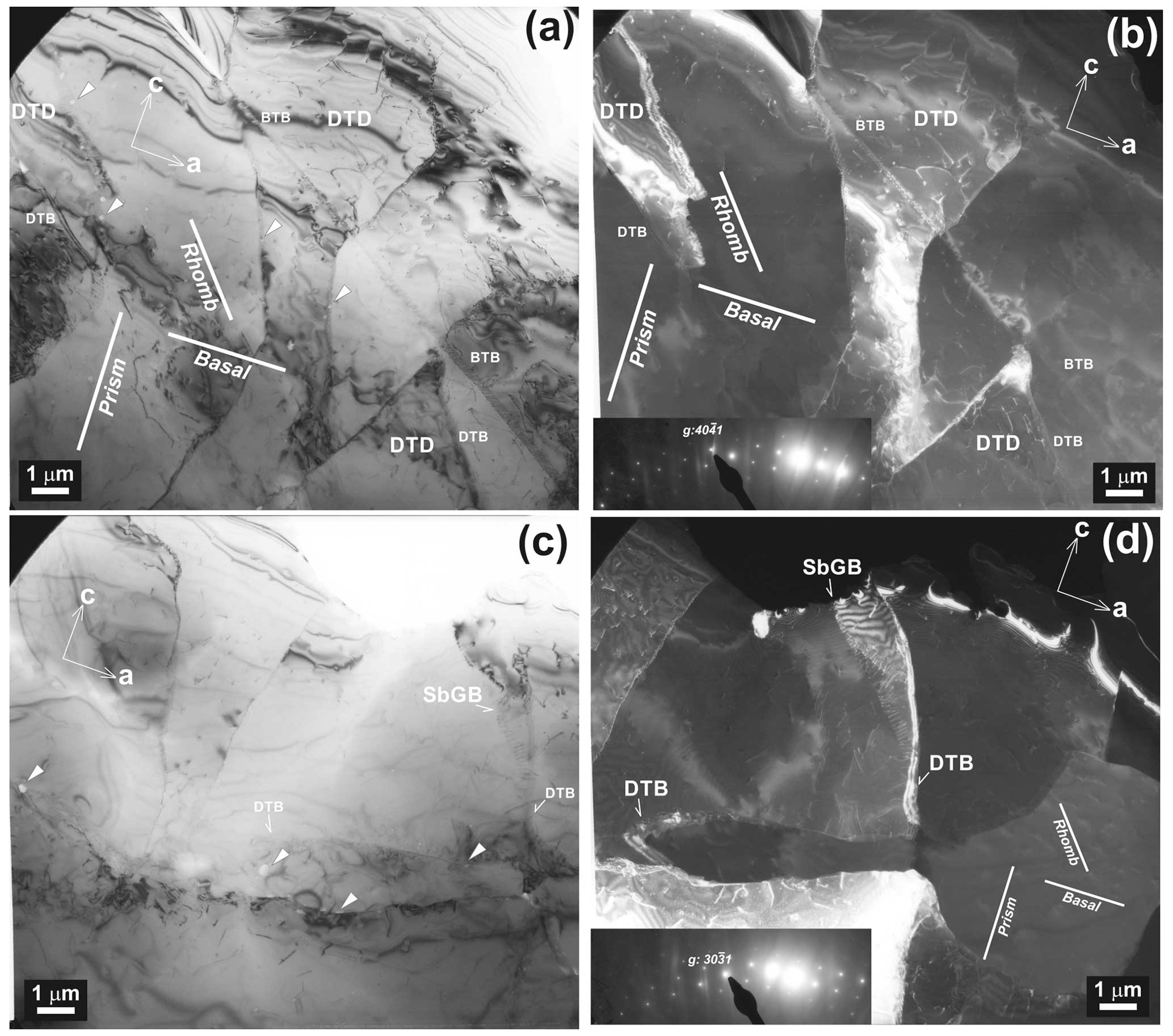
Figure 13An example of a transformation from pristine Dauphiné twin boundaries (DTBs) to low-angle boundaries in the same quartzite. (a) Bright-field image. (b) Dark-field TEM images with . (c) Dark-field TEM image with . Fluid inclusions (indicated by white arrowheads) exist along the DTBs. (d) Dark-field TEM image with . The directions of visible dislocation lines are nearly vertical not along the a-axis but along the c-axis direction. The lower-left insets in (b) and (c) are the corresponding selected area electron diffraction patterns. The traces of the crystallographic planes of the quartz are indicated as “Basal”, “Prism”, and “Rhomb” as in Fig. 8. DTD and BTB are Dauphiné twin domain and Brazil twin boundary, respectively.
5.1 The ooECCI provides reasonable contrasts in a pair of DT domains
The ooECCI provides visible contrasts on a pair of DT domains exchanging positive and negative rhombohedral planes, which is confirmed in the further TEM imaging and electron diffraction techniques. The ECCI technique based on backscattered electron imaging is one of the practical tools to observe DT domains and boundaries directly at medium magnifications (up to 10 000 times magnification) with a SEM, while a dark-field TEM provides more detail of microstructures and textures with surrounding dislocations with a Burgers vector determination at high magnification. The combination of both imaging techniques is a powerful tool to reveal the interactions between the twinning and dislocation mobility in a deformed quartz.
5.2 Rhombohedral slip activated near a DT boundary in quartz
The thickness contour fringe WBDF TEM method was applied for the Burgers vector determination to identify an active slip system operated at a nearby DT boundary in a deformed quartz. Rhombohedral slip should play an important role for quartz during plastic deformation in the pervasively twinned regions, although a statistic measurement of the relative distributions of positive and negative rhombohedral slip systems (i.e. not only slip plane but also slip direction) on a Dauphiné twinned quartz in conventional EBSD techniques is difficult. The TEM analysis of individual dislocations near a DT boundary, by distinguishing positive and negative rhombohedral planes from the structure factors in the precession electron diffraction (Fig. S4), can contribute to the understanding of the role of rhombohedral slip on dislocation glide of a Dauphiné twinned quartz.
All the data of this research are presented in the paper, and additional material has been uploaded as a Supplement.
The supplement related to this article is available online at: https://doi.org/10.5194/ejm-36-709-2024-supplement.
NM designed the research. NM and DSS carried out the observation with the SEM and TEM. NM, DSS, and FH prepared the manuscript with contributions from all co-authors.
At least one of the (co-)authors is a member of the editorial board of European Journal of Mineralogy. The peer-review process was guided by an independent editor, and the authors also have no other competing interests to declare.
Publisher's note: Copernicus Publications remains neutral with regard to jurisdictional claims made in the text, published maps, institutional affiliations, or any other geographical representation in this paper. While Copernicus Publications makes every effort to include appropriate place names, the final responsibility lies with the authors.
This article is part of the special issue “Probing the Earth: experiments on and for our planet”. It is a result of the EMPG 2023 conference, Milan, Italy, 12–15 June 2023.
Funded by the open-access publishing fund of the University of Bayreuth. We appreciate the DFG for funding the FIB facility (grant INST 91/315-1 FUGG) and the TEM facility (grant INST 91/251-1 FUGG) at Bayerisches Geoinstitut, Universität Bayreuth. Two anonymous reviewers and the editor are thanked for their very detailed and constructive reviews.
This research has been supported by the Deutsche Forschungsgemeinschaft (grant nos. INST 91/315-1 FUGG and INST 91/251-1 FUGG).
This paper was edited by Paola Comodi and reviewed by two anonymous referees.
Barber, D. J. and Wenk, H. R.: Dauphiné twinning in deformed quartzites: Implications of an in situ TEM study of the α-β phase transformation, Phys. Chem. Miner., 17, 492–502, https://doi.org/10.1007/BF00202229, 1991.
Cordier, P. and Doukhan, J. C.: Plasticity and dissociation of dislocations in water-poor quartz, Philos. Mag. A, 72, 497–514, https://doi.org/10.1080/01418619508239935, 1995.
Cordier, P., Morniroli, J. P., and Cherns, D.: Characterization of Crystal Defects in Quartz by Large-Angle Convergent-Beam Electron-Diffraction, Philos. Mag. A, 72, 1421–1430, https://doi.org/10.1080/01418619508236266, 1995.
Cocuzzi, D. A. and Laughner, J. W.: Effects of surface abrasion and impurity levels on stress-induced Dauphine twinning in alpha quartz, Proceedings of the 43rd Annual Symposium on Frequency Control, Denver, CO, USA, 31 May–2 June 1989, pp. 617–622, https://doi.org/10.1109/FREQ.1989.68923, 1989.
Goltrant, O., Cordier, P., and Doukhan, J.-C.: Planar deformation features in shocked quartz; a transmission electron microscopy investigation, Earth Planet. Sc. Lett., 106, 103–115, https://doi.org/10.1016/0012-821X(91)90066-Q, 1991.
Gratz, A. J., Tyburczy, J., Christie, J., Ahrens, T., and Pongratz, P.: Shock Metamorphism of Deformed Quartz, Phys. Chem. Miner., 16, 221–233, https://doi.org/10.1007/BF00220689, 1988.
Hamers, M. F., Pennock, G. M., and Drury, M. R.: Scanning electron microscope cathodoluminescence imaging of subgrain boundaries, twins and planar deformation features in quartz, Phys. Chem. Miner., 44, 263–275, https://doi.org/10.1007/s00269-016-0858-x, 2017.
Heidelbach, F., Kunze, K., and Wenk, H. R.: Texture analysis of a recrystallized quartzite using electron diffraction in the scanning electron microscope, J. Struct. Geol., 22, 91–104, https://doi.org/10.1016/S0191-8141(99)00125-X, 2000.
Ishida, Y., Ishida, H., Kohra, K., and Ichinose, H.: Determination of the Burgers vector of a dislocation by weak-beam imaging in a HVEM, Philos. Mag. A, 42, 453–462, https://doi.org/10.1080/01418618008239369, 1980.
Jacob, D. and Cordier, P.: A precession electron diffraction study of α, β phases and Dauphiné twin in quartz, Ultramicroscopy, 110, 1166–1177, https://doi.org/10.1016/j.ultramic.2010.04.010, 2010.
Lloyd, G. E.: Grain boundary contact effects during faulting of quartzite: an SEM/EBSD analysis, J. Struct. Geol., 22, 1675–1693, https://doi.org/10.1016/S0191-8141(00)00069-9, 2000.
Lloyd, G. E., Alsop, G. I., Holdsworth, R. E., McCaffrey, K. J. W., and Hand, M.: Microstructural evolution in a mylonitic quartz simple shear zone: the significant roles of dauphine twinning and misorientation, in: Flow Processes in Faults and Shear Zones, Geological Society of London, 224, 39–61, https://doi.org/10.1144/gsl.sp.2004.224.01.04, 2004.
Le Chatelier, H.: Sur la dilatation du quartz, Compt. Rend. Acad. Sri., Paris, 108, 1046–1049, 1889.
Menegon, L., Pennacchioni, G., Heilbronner, R., and Pittarello, L.: Evolution of quartz microstructure and c-axis crystallographic preferred orientation within ductilely deformed granitoids (Arolla unit, Western Alps), J. Struct. Geol., 30, 1332–1347, https://doi.org/10.1016/j.jsg.2008.07.007, 2008.
Menegon, L., Piazolo, S., and Pennacchioni, G.: The effect of Dauphiné twinning on plastic strain in quartz, Contrib. Mineral. Petr., 161, 635–652, https://doi.org/10.1007/s00410-010-0554-7, 2011.
Miyajima, N. and Walte, N.: Burgers vector determination in deformed perovskite and post-perovskite of CaIrO3 using thickness fringes in weak-beam dark-field images, Ultramicroscopy, 109, 683–692, https://doi.org/10.1016/j.ultramic.2009.01.010, 2009.
Miyajima, N., Li, Y., Abeykoon, S., and Heidelbach, F.: Electron channelling contrast imaging of individual dislocations in geological materials using a field-emission scanning electron microscope equipped with an EBSD system, Eur. J. Mineral., 30, 5–15, https://doi.org/10.1127/ejm/2017/0029-2683, 2018.
Miyajima, N., Mandolini, T., Heidelbach, F., and Bollinger, C.: Combining ECCI and FIB milling techniques to prepare site-specific TEM samples for crystal defect analysis of deformed minerals at high pressure, Cr. Geosci., 351, 295–301, https://doi.org/10.1016/j.crte.2018.09.011, 2019.
Mussi, A., Gallet, J., Castelnau, O., and Cordier, P.: Application of electron tomography of dislocations in beam-sensitive quartz to the determination of strain components, Tectonophysics, 803, 228754, https://doi.org/10.1016/j.tecto.2021.228754, 2021.
Pehl, J. and Wenk, H. R.: Evidence for regional Dauphiné twinning in quartz from the Santa Rosa mylonite zone in Southern California. A neutron diffraction study, J. Struct. Geol., 27, 1741–1749, https://doi.org/10.1016/j.jsg.2005.06.008, 2005.
Rahl, J. M., McGrew, A. J., Fox, J. A., Latham, J. R., and Gabrielson, T.: Rhomb-dominated crystallographic preferred orientations in incipiently deformed quartz sandstones: A potential paleostress indicator for quartz-rich rocks, Geology, 46, 195–198, https://doi.org/10.1130/G39588.1, 2018.
Seto, Y. and Ohtsuka, M.: : free and open-source multipurpose crystallographic software integrating a crystal model database and viewer, diffraction and microscopy simulators, and diffraction data analysis tools, J. Appl. Crystallogr., 55, 397–410, https://doi.org/10.1107/S1600576722000139, 2022.
Trepmann, C. A. and Spray, J. G.: Shock-induced crystal-plastic deformation and post-shock annealing of quartz: microstructural evidence from crystalline target rocks of the Charlevoix impact structure, Canada, Eur. J. Mineral., 18, 161–173, https://doi.org/10.1127/0935-1221/2006/0018-0161, 2006.
Trepmann, C. A., Spray, J. G., Kenkmann, T., Hörz, F., and Deutsch, A.: Planar microstructures and Dauphineì twins in shocked quartz from the Charlevoix impact structure, Canada, in: Large Meteorite Impacts III, Geological Society of America, https://doi.org/10.1130/0-8137-2384-1.315, 2005.
Wenk, H.-R., Barton, N., Bortolotti, M., Vogel, S. C., Voltolini, M., Lloyd, G. E., and Gonzalez, G. B.: Dauphiné twinning and texture memory in polycrystalline quartz. Part 3: texture memory during phase transformation, Phys. Chem. Miner., 36, 567–583, https://doi.org/10.1007/s00269-009-0302-6, 2009.
Wenk, H.-R., Yu, R., Vogel, S., and Vasin, R.: Preferred Orientation of Quartz in Metamorphic Rocks from the Bergell Alps, Minerals-Basel, 9, 277, https://doi.org/10.3390/min9050277, 2019.