the Creative Commons Attribution 4.0 License.
the Creative Commons Attribution 4.0 License.
 | 03 May 2024
Comparison between 2D and 3D microstructures and implications for metamorphic constraints using a chloritoid–garnet-bearing mica schist
Fabiola Caso
Alessandro Petroccia
Sara Nerone
Andrea Maffeis
Alberto Corno
Michele Zucali
Despite the fact that rock textures depend on the 3D spatial distribution of minerals, our tectono-metamorphic reconstructions are mostly based on a 2D visualisation (i.e. thin sections). This work compares 2D and 3D investigations of petrography and microstructures, modal abundances, and local bulk rock composition and their implication for P–T estimates, showing the pros and cons and reliability of 2D analysis. For this purpose, a chloritoid–garnet-bearing mica schist from the Dora-Maira Massif in the Western Alps has been chosen. In particular, for 2D a thin section scan has been combined with chemical X-ray maps, whereas for 3D the X-ray computerised axial microtomography (µCT) has been applied. Two-dimensional investigations are readily accessible and straightforward but do not consider the entire rock volume features. Conversely, the rise of 3D techniques offers a more comprehensive and realistic representation of metamorphic features in the 3D space. However, they are computationally intensive, requiring specialised tools and expertise. The choice between these approaches should be based on the research aims, available resources, and the level of detail needed to address specific scientific questions. Nevertheless, despite differences in the modal distribution, the estimated bulk rock compositions and relative thermodynamic modelled phase fields show similarities when comparing the 2D and 3D results. Also, since different thin section cut orientations may influence the results and consequent interpretations, three different cuts from the 3D model have been extrapolated and discussed (i.e. XZ, YZ, and XY planes of the finite-strain ellipsoid). This study quantitatively corroborates the reliability of the thin section approach for tectono-metamorphic reconstructions, still emphasising that 3D visualisation can help understand rock textures.
- Article
(9680 KB) - Full-text XML
-
Supplement
(8751 KB) - BibTeX
- EndNote


The tectono-metamorphic history of three-dimensional (3D) rock volumes relies on thin section two-dimensional (2D) observations to derive equilibrium microstructural relationships between mineral phases, their modal abundances, and thus the calculated bulk rock composition (Vernon, 1977; Palin et al., 2016). The latter is mandatory for reliable quantitative estimation of pressure (P) and temperature (T) equilibration conditions through thermodynamic modelling and isochemical phase diagrams (Tinkham and Ghent, 2005; Brown, 2014; Spear et al., 2016; Holder et al., 2019; Lanari and Duesterhoeft, 2019). However, determining the effective bulk composition that participates in metamorphic reactions is non-trivial (Lanari and Engi, 2017). In fact, even though the microstructure of rocks refers to a 3D spatial distribution, the scientific community, for simplicity, generally investigates them from a 2D point of view (i.e. using thin sections). For example, this can result in underestimation or overestimation of modal proportions of a mineral phase when extrapolating 2D data to a 3D volume (e.g. Heilbronner and Bruhn, 1998). Moreover, textures, grain size, shape, and orientation of different mineral phases in polymineralic rocks are further consequences of 3D heterogeneity. Also, different sample cuts and, thus, different orientations of the thin section and, consequently, of its finite-strain ellipsoid can influence observations and interpretations. Moreover, microstructural parameters also provide important clues not only on the chemical processes (e.g. mineral dissolution, Hartmeier et al., 2024) but also on the physical processes (e.g. rock mechanics and rheology with geodynamic implications; Sun et al., 2017; Giuntoli et al., 2022; Herviou et al., 2023).
Despite the variety of tools that are used by metamorphic petrologists to calculate the local bulk composition of a sample or thin section, each has different limitations (Palin et al., 2016; Sharma et al., 2021; Forshaw and Pattison, 2023b). While bulk rock compositions are obtained by whole-rock geochemical analysis (e.g. X-ray fluorescence, XRF), another approach consists of combining modal abundance estimates of phases with their compositions (e.g. Palin et al., 2016). In particular, a local bulk rock composition may be obtained via a weighted calculation involving the proportions of minerals present in a thin section using different software (e.g. combining modal proportions obtained by analysing a thin section scan or using chemical X-ray maps through JMicroVision software; Palin et al., 2016; or the Quantitative X-ray Maps Analyzer; Ortolano et al., 2018) and their representative compositions and densities, as in XMapTools software (e.g. Lanari et al., 2014). One way to overcome the limitations of 2D investigations of a rock volume, still with a thin-section-based method, could be by investigating mutually perpendicular rock slices (Sharma et al., 2021). Nevertheless, any 2D method is subject to a loss of information.
Three-dimensional modelling and analysis applying X-ray computerised axial microtomography (µCT) can overcome this condition. It is a non-destructive, 3D visualisation of internal phases constituting a rock sample, and it is helpful to visualise, characterise, and quantify internal 3D structures by measuring density contrasts between phases down to the micrometre scale. Several geological cases and topics have been analysed using this technique, including deformation and metamorphic process investigations (e.g. Zucali et al., 2014; George and Gaidies, 2017; Macente et al., 2017; Corti et al., 2019; Montemagni et al., 2020; Petri et al., 2020; Giamas et al., 2022; Gaidies et al., 2023) among other topics within geosciences (see Cnudde and Boone, 2013, and Maire and Withers, 2014, for a review). Detailed investigations on how mineral modal abundance changes as a function of 2D area size have already been explored (e.g. Lanari and Engi, 2017). Despite the rise of the combination of different analytical techniques (e.g. X-ray maps and µCT) and GIS-based tools, which strongly improved our capability of quantitatively constraining microstructural relationships among mineral phases, a comparison between 2D and 3D visualisation to understand possible mismatches is still lacking. Moreover, potential differences in mineral abundance and resulting local bulk rock compositions obtained from different sample cuts have been investigated. In particular, we compared a 2D thin section analysis and 3D volume, also including three different cuts extrapolated from the 3D volume itself (XZ, YZ, and XY planes of the finite-strain ellipsoid of deformation).
This work provides a detailed comparison between 2D and 3D visualisation using a chloritoid–garnet-bearing mica schist from the central-southern sector of the Dora-Maira Massif (DMM, Western Alps; Chopin et al., 1991; Michard et al., 1993). The Dora-Maira Massif, one of the Internal Crystalline Massifs, belongs to the distal part of the Briançonnais palaeomargin, consisting of significant exposures of units with different HP/UHP metamorphic imprints (Groppo et al., 2019; Bonnet et al., 2022; Michard et al., 2022; Manzotti et al., 2022, and references therein). The Dora-Maira Massif is described as a nappe stack made of three major units that, from the bottom to the top, are (i) the Sanfront-Pinerolo Unit (SPU; Vialon, 1966; Avigad et al., 2003; Petroccia and Iaccarino, 2022), (ii) the Dora-Maira Basement Complex (Michard et al., 1993), and (iii) the Dronero Unit (DU; Michard et al., 2022). A ductile tectonic contact separates the monocyclic unit (SPU) from the overlying units of the Dora-Maira Basement Complex (Avigad et al., 2003; Nerone et al., 2024). The sampling site (BAR-38A sample: 44°41′37.65′′ N, 7°14′11.02′′ E) is located in the Dora-Maira Basement Complex, specifically in one of its HP units, the Ricordone Unit. This study aims to highlight the pros, cons, and similarities between 2D and 3D visualisation to examine the reliability of the 2D approaches generally used in metamorphic investigations necessary for geodynamic interpretations.
To describe the structural elements of the studied samples without interpretations from the previous investigations, which is not proper for the purpose of this work, the deformation events and structural elements are numbered relative to the principal event (e.g. Sp, Sp-1/pre-Sp), where the suffix “p” denotes “principal”. Abbreviations are (S) for foliation surfaces or axial plane foliation and (D) for the deformation phases.
The thin section used for the 2D microstructural analysis has been cut parallel to the lineation and perpendicular to the main foliation, representing the XZ plane of the finite strain (Turner and Weiss, 1963). The µCT has been conducted by scanning a cylinder (Fig. 1; 2.2 cm in diameter and 1.5 cm in height) within the rock volume from which the thin section has been produced. The uppermost base of the cylinder is partly included in the same surface of the thin section (Fig. 1). Mineral abbreviations are after Warr (2021), except for Wm, which stands for white mica. Microstructures have been described and classified according to Passchier and Trouw (2005).
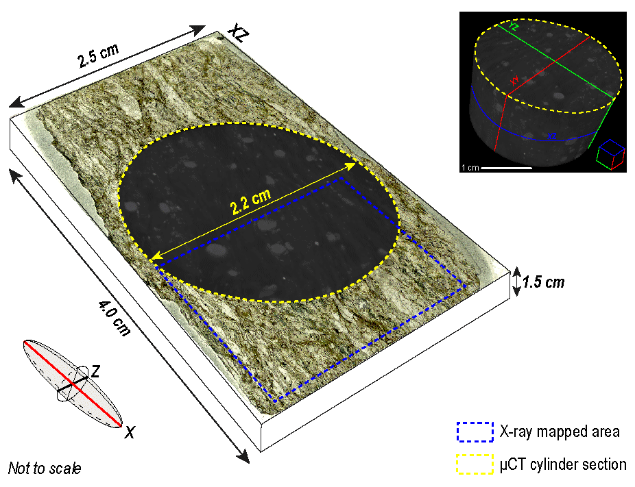
Figure 1Thin section scan with reported X-ray map (blue polygon) and µCT upper face scan (yellow polygon) mapped areas. The dimensions of the thin section, the mapped area, and the scanned cylinder are reported. The three extrapolated cuts from the µCT cylinder (XZ, YZ, XY) are reported in the top-right corner.
2.1 Two-dimensional quantitative analysis
The 2D quantitative microstructural analysis was carried out using the Micro-Fabric Analyzer ArcGIS toolbox (MFA; Visalli et al., 2021) to obtain a vectorial segmented map of the mineral boundaries. The MFA allows extracting a statistically meaningful number of 2D microstructural data from their shape parameters or grain orientations (e.g. width and length, roundness, perimeter; see Appendix A in Visalli et al., 2021, for an explanation of each calculated parameter). In detail, the MFA toolbox comprises (i) the Grain Size Detector (GSD) tool, which traces vectorial polygonal grains contouring maps by processing a high-resolution optical thin section scan acquired in cross-polarised light (XPL hereafter); (ii) the Quantitative X-ray Maps Analyzer tool (Q-XRMA; Ortolano et al., 2018), which returns a mineral classified map obtained from chemical X-ray maps processing; (iii) the Mineral Grain Size Detector (Min-GSD; Visalli et al., 2021), which merges the outputs obtained from the GSD and Q-XRMA to label the polygon of each grain with its relative mineral phase name (Grt, Cld, etc.), since the GSD tool alone is not able to discriminate grains of different mineral phases without the chemical input (i.e. the chemical X-ray maps; see Caso, 2023, and Caso et al., 2024, for a practical example).
The thin section scan used in the GSD tool was acquired by using an Epson V750 dual-lens system scanner at the Dipartimento di Scienze della Terra “A. Desio”, Università degli Studi di Milano (Italy). The scan has 24 bit depth and 4800 dpi resolution, corresponding to a pixel size of ∼ 5.29 µm. The X-ray maps and quantitative mineral spot analyses were obtained with the electron microprobe analyser (EPMA) JEOL 8200 Super Probe equipped with five wavelength-dispersive spectrometers (WDS) at the Dipartimento di Scienze della Terra “A. Desio”, Università degli Studi di Milano. Quantitative X-ray maps have been acquired using a beam current of 100 nA, with a dwell time of 30 ms and a resolution of 600 × 700 pixels (30 µm of step size). All element maps (i.e. Si, Ti, Al, Fe, Mn, Mg, Ca, Na, K, P) have been acquired with two cycles of WDS-detector mapping. An accelerating voltage of 15 keV and a beam current of 50 nA were used for mineral analyses. Integrating X-ray maps (spatial resolution of 30 µm) with high-resolution thin section scan (5.29 µm of pixel size) allows increasing the final resolution of the computed mineral grain boundary map, thus allowing separating grains smaller than 30 µm, with a lower limit of ∼ 5.29 µm.
Twelve shape parameters have been obtained from quantitative analysis (see Table S1 in the Supplement for all data). Among these, two help discriminate different fabrics (i.e. Sp, Sp-1, post-Sp) or mineral generations: the long-axis orientation and the shape_area parameter. The former is the angle (degrees) of the grain long axis measured clockwise with respect to a vertical reference axis (in this case perpendicular to the Sp foliation) with values from 0 to 180°; grains making anisotropies tend to have clusters of orientations reflecting specific fabrics (Sp, Sp-1, etc.). The latter is the area of each grain expressed in square pixels based on the scan spatial resolution (px2) and helps distinguish different mineral generations based on grain size clusters.
2.2 Three-dimensional quantitative analysis
Tomographic data were obtained using an X-ray computerised axial microtomography (µCT) Zeiss Xradia 510 Versa at the University of Granada, in the Centre for Scientific Instrumentation (Granada, Spain). This equipment allows the visualisation of distribution patterns of materials with different attenuation values (depending on density) through a reconstruction of sets of parallel cross sections perpendicular to the axis of rotation within the scanner. The following settings were established for the analysed samples: objective = 0.4×, voltage = 140 kV, power = 10 W, binning = 1, filter = HE4, exposure time = 18 s, voxel size = 11.40 µm, and the number of projections = 3201. The voxel size is the three-dimensional pixel size within the scanned volume, and it determines the spatial resolution of the reconstructed 3D image. A smaller voxel size means higher spatial resolution, allowing the visualisation of smaller details within the object. However, a smaller voxel size also requires more data to be acquired and processed, increasing scanning time and computational demands. Thus, with the performed µCT scan, only mineral phases bigger than ∼ 12 µm are detectable. Image reconstruction was done using Reconstructor Scout and Scan™ software (Zeiss). Dragonfly Pro™ (Object Research System) was used to perform advanced post-processing analysis and 3D image data, perform phase segmentation by creating a region of interest (ROI), and obtain the final 3D mesh of each rock-forming mineral phase. In this way, it is possible to quantify the volume proportion (as vol %) of the detectable and visible mineral phases in the analysed rock specimen. Finally, to investigate the possible influence of differently oriented 2D cuts, we extrapolated through the clip tool of Dragonfly Pro™ from the 3D output three different oriented planes (XZ, YZ, XY; see Fig. 1 for the cuts orientations), passing through the centre of the cylinder, with a ∼ 30 µm thickness.
2.3 Local bulk rock composition
The local bulk rock composition was calculated by mass balancing the normalised mineral modes (i.e. removing the accessory phases <2 vol %) in the 2D thin section, in the extrapolated cuts from 3D (XZ, YZ, XY; see Fig. 1), and in the whole 3D volume with mineral chemistry inferred from the EPMA–WDS spot analyses and considering the molar volumes of each phase. See Table S2 for the complete dataset of EPMA–WDS spot analyses and Table S3 for both the 2D and 3D modal estimation (normalised and not) and the obtained local bulk rock compositions. Molar volumes of each mineral (data from Holland and Powell, 2011) were used to convert the observed mineral modes (vol %) in mole percent (mol %) of each phase. The measured mineral compositions (mol % of each endmember) were then used to convert the mol % of each phase into mol % of each oxide component, following the same approach as Nerone et al. (2023). White mica endmember mol % estimation was improved to consider the celadonitic exchange. An average composition of each phase has been used to compare the local bulk rock compositions obtained from 2D vs. 3D modal amounts. Garnet and white mica are the only chemically zoned phases whose zoning modal proportions are not quantifiable in the 3D classification as they display the same density.
Sample BAR-38A is a garnet–chloritoid-bearing mica schist (see Fig. S1 in the Supplement for more photos about sample petrography and microstructures). This sample exhibits a spaced anastomosed composite foliation Sp defined by the alternation of heterogeneously distributed millimetre-thick layers of white mica-rich domains and elongated quartz layers (Fig. S1a).
Garnet occurs as coarse (Grt-C; Fig. 2a) and finer (Grt-F; Fig. 2b) grains, recognisable both in the thin section (Fig. S1b) and in the µCT cylinder. Grt-C grains are pluri- to millimetric grains showing a well-developed chemical zoning (inferred from the X-ray maps and spot analyses) that defines a core and a rim (see Fig. 2c for the Ca example), characterised by (i) a decrease in Ca content from core (XGrs = 0.19) to rim (XGrs < 0.01), (ii) a decrease in Mn from core (XSps = 0.07) to rim (XSps = 0.01), (iii) an increase in Mg from core (XPrp = 0.05) to rim (XPrp = 0.12), and (iv) an increase in Fe from core (XAlm = 0.72) to rim (XAlm = 0.85). Grt-F is compositionally homogeneous, with a chemical composition equal to the rim of Grt-C. Thus, garnet is almandine-rich (Fig. 2d). Inclusions are mainly concentrated in Grt-C cores but are less abundant in Grt-C rims. Cores contain monocrystalline inclusions of white mica, rutile, quartz, chloritoid, and polymineralic aggregates of paragonite ± epidote ± white mica. Such aggregates have been previously reported in other HP rocks from the Western Alps (e.g. Fe–Ti eclogitic metagabbros from Monviso, Groppo and Castelli, 2010; metapelites from the DMM, Manzotti et al., 2022) and are interpreted as pseudomorphs after lawsonite. The occurrence of chloritoid as an inclusion within Grt-C is visible in the 3D reconstruction, whereas only one small grain has been detected in the thin section. Grt-F is subhedral, corresponding to small crystals that are mostly inclusion-free. These grains slightly overgrow the pre-existing Sp foliation, pointing to partial growth after Dp, and could be correlated with the Grt-C rims (Fig. S1c). Relationships between the internal foliation Sp-1 and the Sp, and the slight overgrow of garnet on the Sp, suggest that garnet could be interpreted as inter-tectonic to post-tectonic with respect to the Dp deformational event. Moreover, from a quantitative point of view, the two garnet types can be distinguished through the shape parameter obtained with the MFA tool. Integrating petrographic and MFA data, the Grt-F area (in blue in Fig. 2e) ranges from 0 to ∼ 3600 px2, while Grt-C (in red in Fig. 2e) is between ∼ 3600 and 45 000 px2. From 2D analysis, the modal proportions between Grt-C and Grt-F are 65 % and 35 %, respectively (Fig. 2e). The long-axis orientations of the garnet show scattered values (see Fig. S2) due to its isotropic shape, making garnet not suitable for marking any isoriented structure.
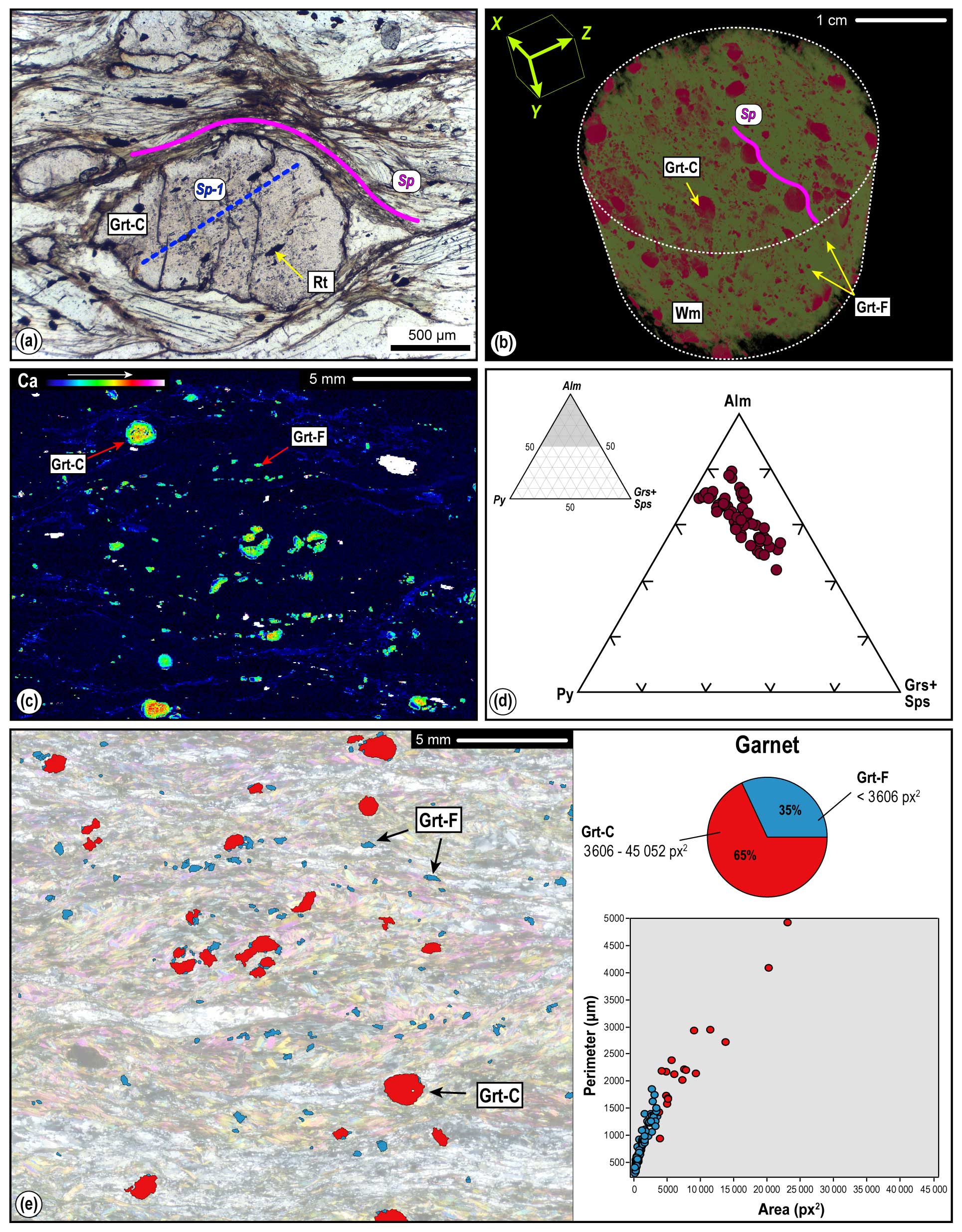
Figure 2(a) Grt-C with the inclusion-rich core highlighting an internal foliation Sp-1, at high angle with respect to the Sp foliation wrapping the whole Grt (PPL: plane-polarised light); the Grt-F is fine-grained. (b) Three-dimensional cylinder of the sample showing the distribution of both Grt-C and Grt-F crystals in purple. (c) X-ray map showing the Ca intensities and highlighting Grt compositional zoning with a core and rim. (d) Ternary plot showing Grt composition. (e) Grt map showing the bimodal grain size (coarser Grt-C in red and finer Grt-F in blue), their modal abundance, and a scatter graph showing area vs. perimeter of Grt grains.
Chloritoid is heterogeneously distributed both in the thin section and in the µCT cylinder (Fig. 3a). Different generations of chloritoid have been observed: (i) a first generation is preferentially oriented in microlithons defining the earlier Sp-1 foliation (Fig. 3b); (ii) a second generation, up to 1 mm in length, is aligned along the main foliation or rarely in the garnet strain shadows and marks the Sp (Figs. 3b, S1d, e). Also, mostly in the 3D reconstruction, chloritoid can be recognised within strain shadows around garnet crystals and along the Sp, as well as included in Grt-C, indicating a Dp syn-kinematic growth. X-ray mapping does not show any meaningful chemical difference between the chloritoid generations, and the chemical diagram shows a rather restricted composition (XMg = 0.20–0.21; Fig. 3c). Nevertheless, the textural differences are quite evident from quantitative MFA grain data. Chloritoid long-axis orientations, measured from a vertical reference, are mostly within ∼ 60 and 120°, thus highlighting the Sp foliation (Fig. 3d). However, Sp is locally irregular and anastomosed, especially when perturbed by garnet porphyroblasts, thus producing a slight scattering around the ideal 90°. Grains oriented at 60 or 120° generally demark the limbs of the Sp-1 folds within microlithons. This is evident in the rose diagram in Fig. 3b, which plots only data from a selected microsite of the 2D analysed sample where the overprinting relationships between Sp-1 and Sp are well preserved. The minor clusters at ∼ 15 and ∼ 150–180° represent chloritoid grains in the hinges of folded Sp-1 (see rose diagram zoom in Fig. 3b). A relation between the chloritoid grain size (measured in square pixels) and its long-axis orientation is evident: most of the bigger grains tend to be oriented at ∼ 90° and define the main Sp foliation, whereas smaller and more scattered – in orientation – grains define the Sp-1 (see the scatter diagram on the right side in Fig. 3d).
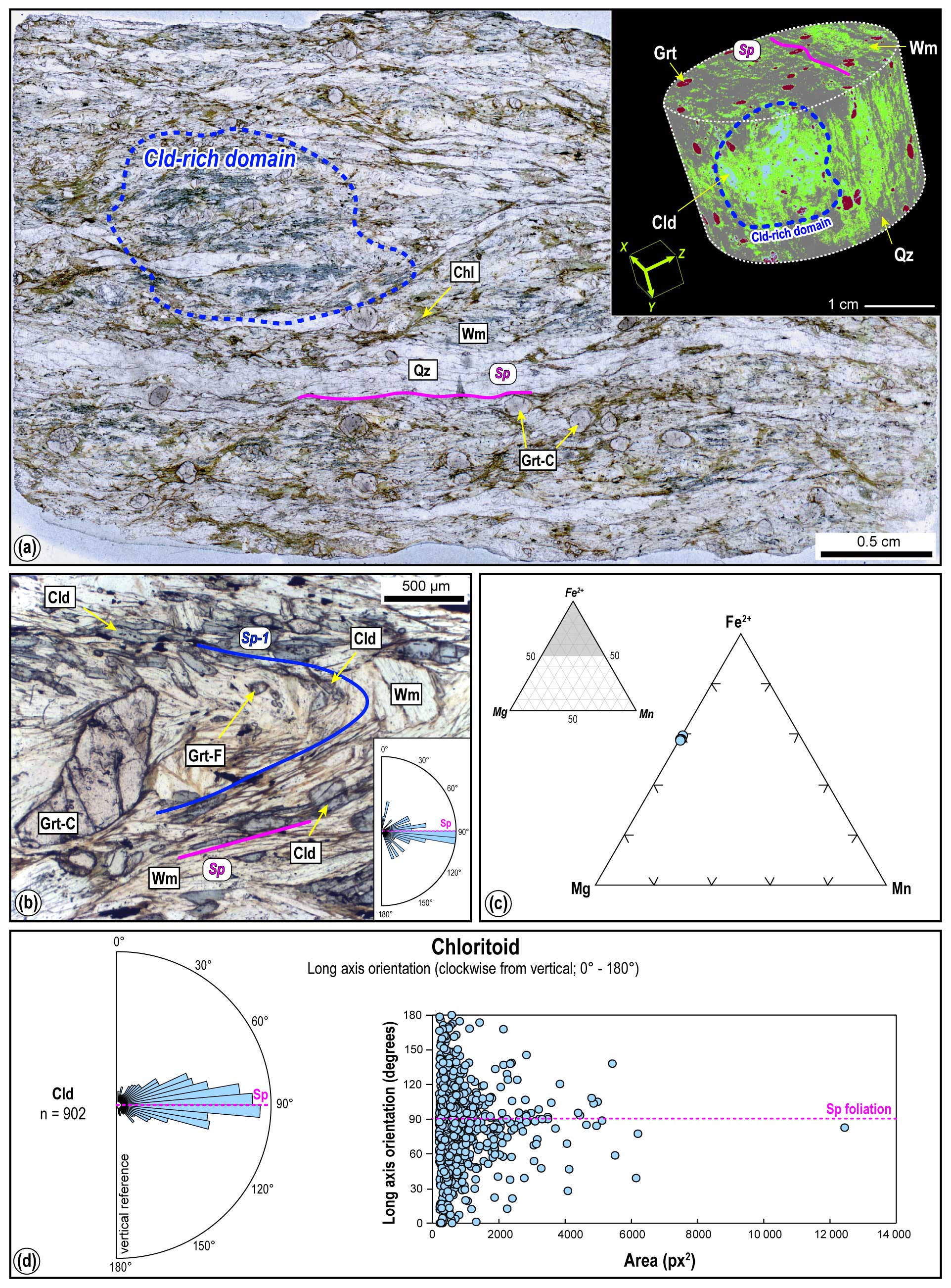
Figure 3(a) Thin section PPL scan showing the main phases of the sample and the chloritoid-rich domain; in the top-right side, the chloritoid distribution within the scanned cylinder is shown. (b) Sp-1 relict foliation in a microlithon, defined by white mica and chloritoid (PPL), and rose diagram showing orientations of chloritoid only extracted from the selected microsite. (c) Ternary plot showing chloritoid chemical compositions. (d) Left part: rose diagram showing the long-axis orientation of chloritoid with respect to a vertical reference measured clockwise (data from the whole 2D map); right part: scatter diagram showing the relation between the long-axis orientation of the chloritoid and grain area (data from the whole 2D map).
K-white mica and minor paragonite heterogeneously occur in scattered domains, recognisable in 2D and 3D visualisations (Fig. 4a). K-white mica marks both the main foliation Sp (Fig. 4b) and the Sp-1, with the latter found in microlithons or inside Grt-C, and rarely statically overgrows the Sp (Fig. S1f). White mica is compositionally variable with Si = ∼ 3.31–3.65 a.p.f.u. (atoms per formula unit; Fig. 4c). Paragonite statically overgrows the Sp, as it is observable in the thin section photo (Fig. 4b) and in the Na X-ray map (Fig. 4d). The static growth of paragonite is particularly evident in the long-axis orientation map (Fig. 4b, e). In particular, most of the K-white mica and a few paragonite grains are marked by a yellow to greenish colour, meaning they are oriented at ∼ 85–90° with respect to the vertical reference, thus aligned along the Sp main foliation. Conversely, most red and blue grains correspond to paragonite, whose long axis is oriented at ∼ 20 or ∼ 180° (Fig. 4e, f). The statistically different orientations of paragonite and K-white mica (i.e. the number of grains aligned parallel or not to the Sp) are also easily observable both in the thin section and in the rose diagrams of the long-axis orientations (Fig. 4f). K-white mica has a well-defined orientation cluster at ∼ 80–100°, representing the Sp foliation; paragonite shows three main clusters: one at ∼ 80–100° marking the Sp and two at ∼ 25–30 and ∼ 150–180°, respectively, particularly evident in the rose diagram zoom of the shown microsite in Fig. 4b. Both K-white mica and paragonite show a strict relationship between long-axis orientations and grain size coarsening: coarser grains tend to mark the Sp foliation (Fig. 4g).
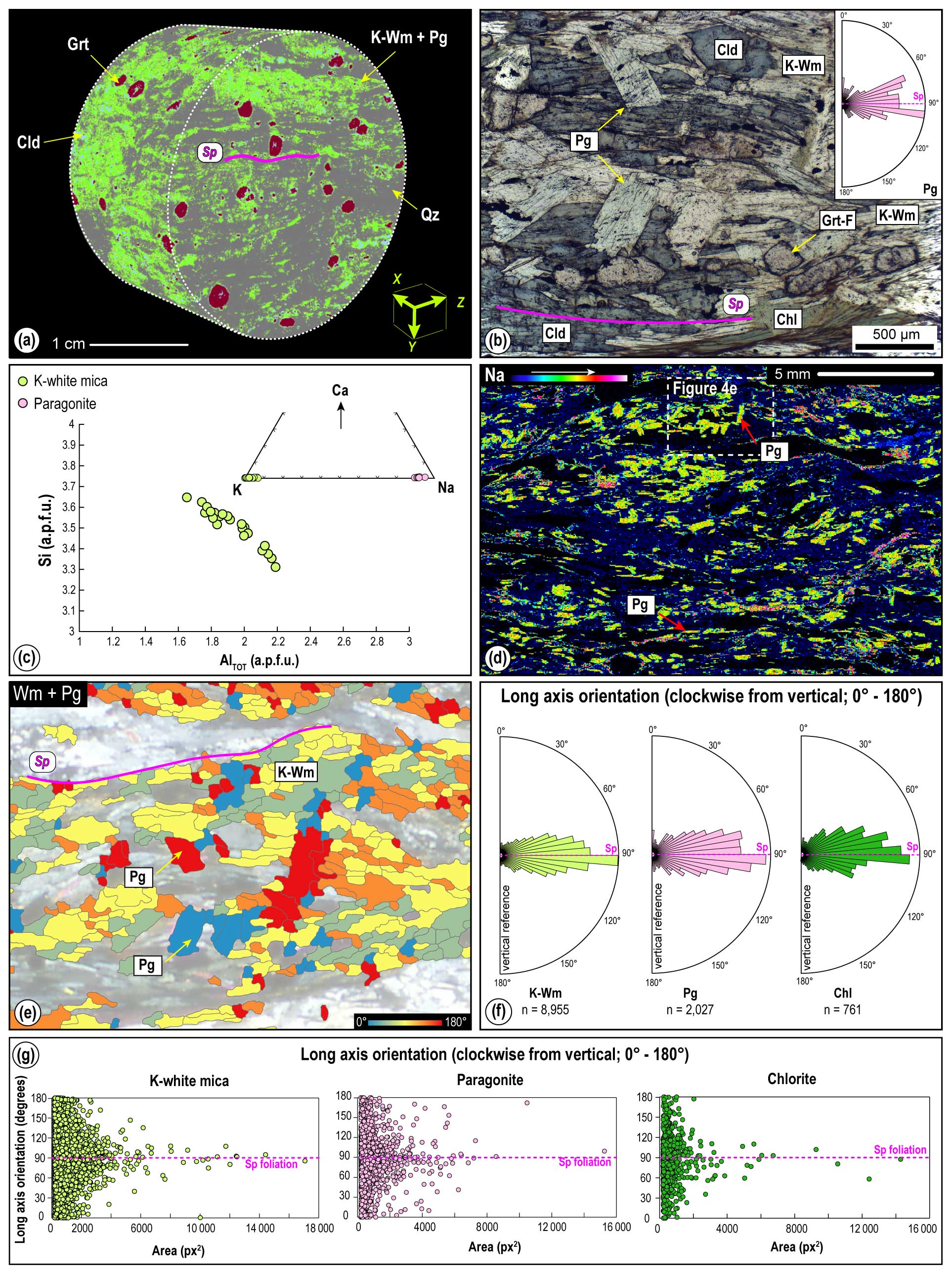
Figure 4(a) Three-dimensional cylinder showing the main foliation made by the isorientation of K-white mica and paragonite. (b) K-white mica growing along the Sp main foliation and paragonite crystals statically growing on the Sp (PPL); on the right side, a rose diagram plotting paragonite grain orientations only for the photo microsite is shown. (c) Si vs. Al a.p.f.u. in a white mica plot and ternary plot in which the distinction between K-white mica and paragonite is appreciable. (d) X-ray map showing the Na intensities and highlighting paragonite both along the main Sp foliation and statically growing. (e) Polygonal map of K-white mica and paragonite classified on the base of their long-axis grain orientations; most of the K-white mica crystals have orientation at ∼ 90°, whereas paragonite crystals are mainly those in red and blue, with orientations at ∼ 20 and ∼ 180° respectively. (f) Rose diagrams showing the long-axis orientations of K-white mica, paragonite, and chlorite. (g) Scatter diagrams showing the relation between the long-axis orientation and grain area of K-white mica, paragonite, and chlorite.
Chlorite is recognised mainly as fan-like aggregates perpendicular to the main foliation or within Grt-C fractures, indicating that this mineral mostly grew post-kinematically with respect to the Dp stage. Chlorite displays a composition of XMg = 0.42–0.45 (Table S2). A main orientation cluster occurs at ∼ 70–100° but with a relatively high number of scattered orientations, representing static or radial aggregates (Fig. 4f, g).
Biotite grows in garnet strain shadows and is locally recognisable along the main foliation. Texturally late chlorite partially replaces biotite. Few biotite relict crystals, recognisable in both 2D and 3D visualisations, show XMg = 0.28–0.46 (Table S2). Lozenge-shaped aggregates of chlorite + albite + quartz are recognisable. Their shape and mineral assemblage could suggest pseudomorphs after sodic amphibole, as reported in other HP Alpine units (e.g. Manzotti et al., 2022). The occurrence of plagioclase is recognisable in both 2D and 3D visualisations, whereas minor phases, e.g. apatite or amphibole, are recognisable only in 2D analyses, as the voxel size is larger than these phases.
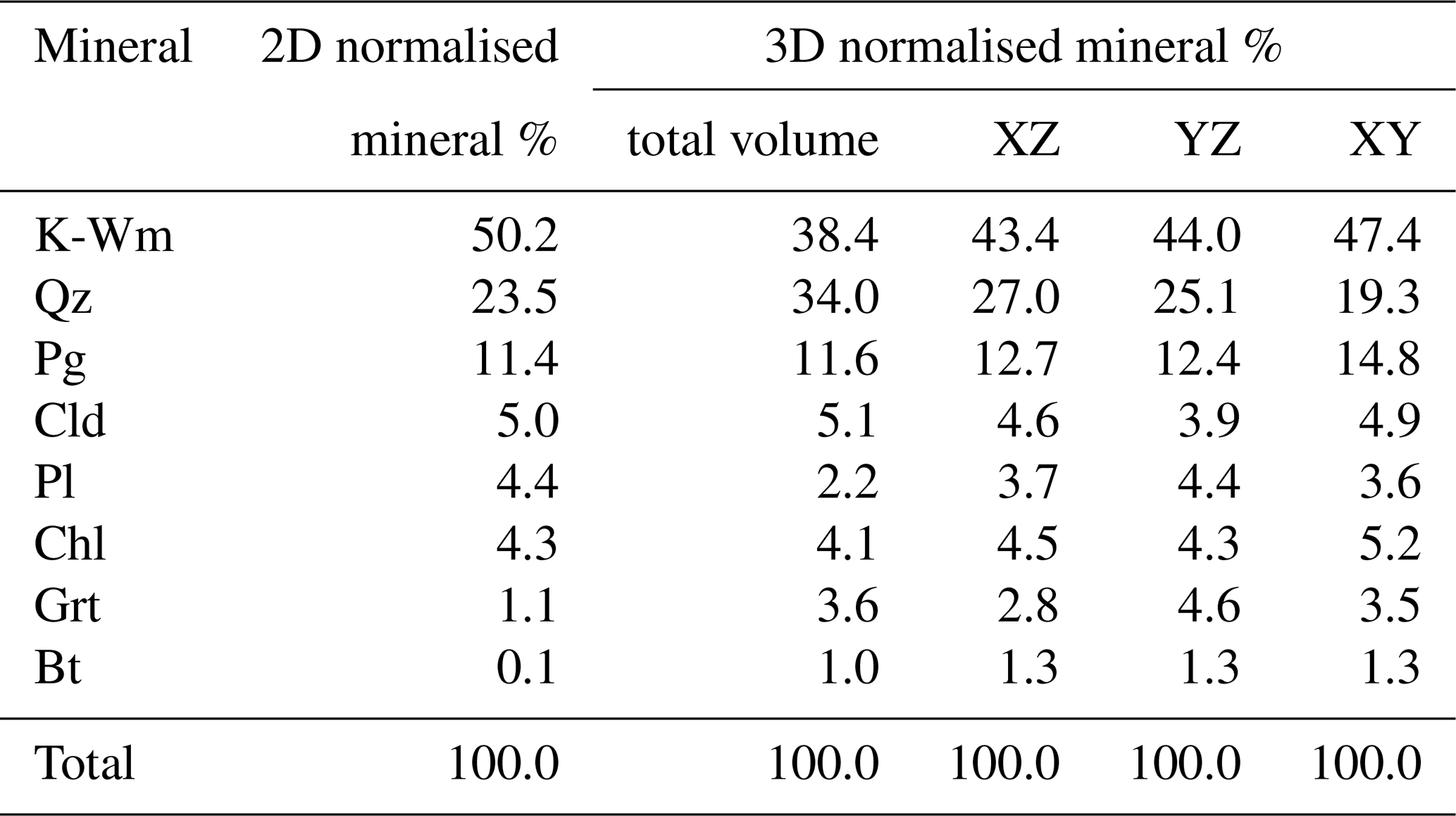
Figure 5 shows the classified MFA mineral grain map and µCT scan representing the phase modal distribution. The whole dataset of 2D classification of the thin section, obtained by combining the X-ray maps in the Q-XRMA tool, and of 3D volume classification is reported in Table S3. The normalised 2D and 3D (total volume, XZ, YZ, XY cuts) modal estimations, thus removing the phases non-detected and classifiable with the 3D technique in the 2D estimations (i.e. apatite and amphibole), and removing the non-classifiable pixels in the 3D scan, are reported in Table 1.
Table 1Normalised modal estimation (vol %) for the 2D thin section; 3D volume; and XZ, YZ, and XY cuts from the volume.
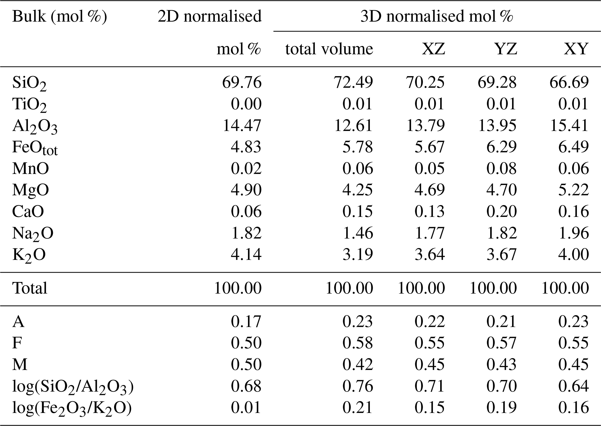
The obtained local bulk rock composition (in mol %) using the normalised modal distribution mass balanced with the chemistry and the density of the different phases in 2D and 3D analysis and the different cuts (Fig. 6b) are reported in Table 2. The full dataset is reported in Table S3.
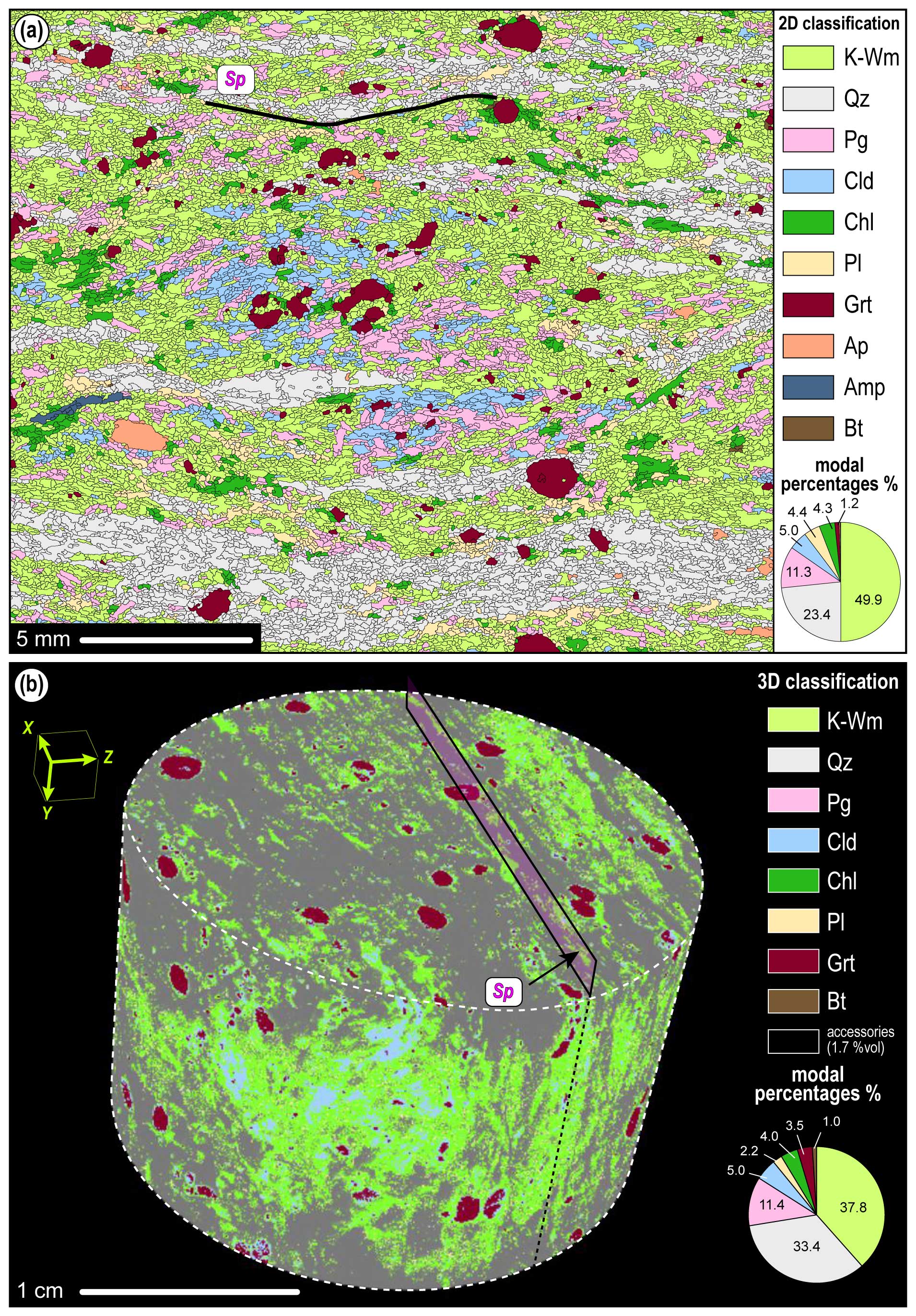
Figure 5(a) 2D classified thin section using MFA displaying the modal distribution and vol % of the mineral phases. (b) 3D classified cylinder displaying the modal distribution and vol % of the main mineral phases.
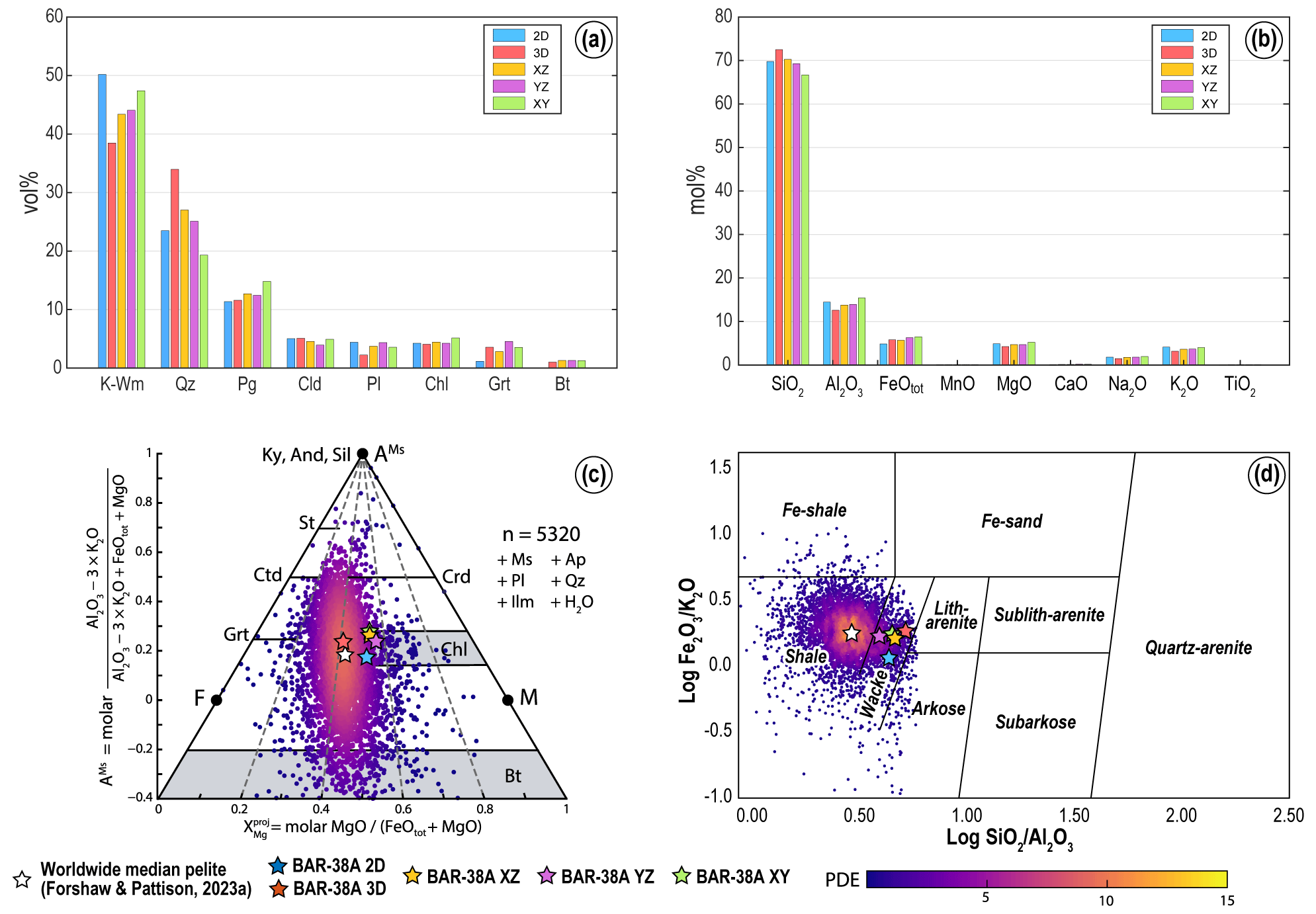
Figure 6(a) Modal proportion (vol %) of major phases in 2D vs. 3D and the extrapolated XZ, YZ, and XY cut. Differences are particularly evident for K-white mica, quartz, garnet, and plagioclase. (b) Local bulk rock composition (mol %) calculated with 2D and 3D estimated mineral modes. Variations in SiO2, Al2O3, K2O, and FeOtot reflect the K-white mica, quartz, and garnet modal differences. (c, d) 2D, 3D and the extrapolated XZ, YZ, and XY local bulk rock compositions in the AFM diagram and in the chemical classification diagram SandClass3 of Herron (1988) compared to the worldwide median pelite of Forshaw and Pattison (2023a). Data were coloured using the plasma colour scheme according to the probability density estimate (PDE).
Table 2Local bulk rock composition (mol %) for the 2D thin section; 3D volume; and XZ, YZ, and XY cuts from the volume, as obtained from the combination of mineral modes and average composition of each phase. Logarithmic ratios have been calculated in weight percent (wt %; following Herron, 1988), and, as such, Fe2O3 has been estimated by using the simple relation Fe2O3 = FeOtot × 0.8998.
Using a chloritoid–garnet-bearing mica schist from the Western Alps, this work compares 2D and 3D sample analysis approaches to provide pros and cons and test the reliability of the commonly used 2D approach thought to be representative of the 3D rock volume.
5.1 Modal distribution
The obtained modal distribution of the major phases reveals similar results in 2D and 3D and extrapolated XZ, YZ, and XY planes from the 3D, but with few differences that need to be discussed (Fig. 6a). K-white mica vol % in the 2D thin section and the three cuts from the 3D volume are similar (up to ∼ 5 % vol differences). However, values taken from the whole 3D cylinder are up to ∼ 10 % lower (Fig. 6a). This mismatch could be related to the geometry of the anastomosed and spaced Sp foliation in sample BAR38-A. As a complementary phase in the foliation, quartz is more abundant in the 3D volume than in any 2D cut, with a difference of more than ∼ 10 % vol (Fig. 6a). The partitioning between layers rich in quartz and layers rich in K-white mica may control the heterogeneous distribution of these mineral phases. This is particularly true for the discrepancies between the 2D thin section (top of the cylinder) and the XZ cut of the 3D volume, which passes through the centre of the cylinder. Here, quartz modal abundance is inversely proportional to that of K-white mica. Paragonite is mostly similar in the different estimations and is slightly overestimated in the XY extrapolation, which could be due to larger lamellae along the main foliation. For the mica group, due to their lamellar habit, three different modal abundances are also expected in the three orientations of the finite-strain ellipsoid (i.e. planes of the finite-strain ellipsoid). Chloritoid is less abundant only in the YZ extrapolation, as it is the only cut perpendicular to its long axis. Plagioclase and garnet differences are mainly due to the heterogeneous distribution within the sample. Biotite vol % differences could be explained as the same as garnet and plagioclase. However, it could also be affected by the resolution of the analysis due to its fine grain size. Chlorite is mainly similar in all the estimations (Fig. 6a).
5.2 Local bulk rock compositions and implications for thermodynamic modelling
The obtained local bulk rock compositions from the different modal abundances highlight strong similarities between the applied approaches (Fig. 6b). Small differences in SiO2 and Al2O3 (∼ 2 mol %–3 mol %) and K2O (∼ 1 mol %) match the observed discrepancies between K-white mica and quartz; i.e. the 3D volume has more SiO2 and less Al2O3 and K2O. FeOtot is mainly controlled by garnet modal differences, which is almandine-rich in composition, whereas MgO is less influenced and compensated by chlorite, biotite, and celadonite-rich K-white mica. MnO and CaO display differences <0.1 mol % because they are minor components in garnet. Na2O is similar, probably because paragonite and plagioclase abundances compensate reciprocally. The TiO2 amount comes only from biotite, as Ti-rich phases (e.g. rutile and ilmenite) were smaller than the selected instrument resolution (both in 2D and 3D). To better understand the TiO2 variations between the two methods, higher resolutions for X-ray mapping acquisition and µCT scan are required.
When comparing the obtained local bulk rock compositions in an AFM diagram (Fig. 6c) with the worldwide median pelite (Forshaw and Pattison, 2023a), the 3D estimation falls in the highest PDE (i.e. probability density estimate) field, corresponding almost perfectly to the median pelite. However, the 2D and all other cuts from the 3D volume are shifted toward higher MgO content, reflecting the discrepancies of MgO and FeOtot. The chemical classification SandClass3 (Fig. 6d) of Herron (1988) highlights that all calculated bulk rock compositions display higher SiO2 content than the worldwide median pelite of Forshaw and Pattison (2023a). In particular, the 2D local bulk rock composition has higher Fe2O3/K2O (Fe2O3 calculated as FeOtot × 0.8998; this conversion is required for plotting data and does not have any chemical/redox implication) than the others, reflecting the K-white mica and garnet modal differences. Similarly, the 3D bulk rock composition displays the highest SiO2/Al2O3 values, reflecting the discrepancies between quartz and K-white mica modal abundances. Nevertheless, all the calculated bulk rock compositions fall within the wacke field (Fig. 6d), implying that significant differences may not be present when reconstructing the protolith composition. However, this needs to be tested for other samples and chemical systems.
The effect of different oxide proportions has already been studied in the literature. Caddick and Thompson (2008) highlighted that Al2O3 content in the bulk rock composition controls the occurrence of index minerals, whereas White et al. (2014) demonstrated that MnO and CaO abundances control the garnet stability field. Palin et al. (2016) used a Monte Carlo simulation to account for differences in the modal distribution and described in detail the shifting of reactions in the P–T space. To unravel possible implications when using the 2D thin section simplification to characterise 3D metamorphic rocks with thermodynamic modelling, only exploratory isochemical phase diagrams for the 2D thin section and the 3D volume of our sample have been calculated (Fig. 7). This calculation may suffer from the simplification of the method used to obtain the local bulk composition, i.e. considering an average composition of each phase, whereas chemical zoning is present for garnet. For a more accurate investigation, newly developed methods for extrapolating chemical features to the 3D volume should be applied (e.g. Taylor, 2022). Perple_X 7.1.6 (Connolly, 2009) was used for calculations in the eight-component NKCFMASH (Na2O–K2O–CaO–FeOtot–MgO–Al2O3–SiO2–H2O) system with excess H2O, in the same P–T range as Manzotti et al. (2022). Phase diagrams were calculated with the internally consistent thermodynamic database of Holland and Powell (2011) (ds62) and the equation of state for the binary fluid H2O–CO2 of Holland and Powell (1998) and the same solution models as in Nerone et al. (2024): garnet, chloritoid, staurolite, chlorite, white mica, and biotite (White et al., 2014); clinopyroxene (Green et al., 2007); amphibole (Green et al., 2016); and feldspar (Fuhrman and Lindsley, 1988). Figure 7 highlights some differences mirroring the calculated bulk rock compositions. The 3D topology is simpler than the 2D topology. The lawsonite stability field is the most sensitive: using the 3D calculated bulk rock composition, lawsonite breakdown occurs in a T-dependent reaction at ∼ 480–520 °C, whereas using the 2D composition, its stability field is progressively shrunk toward lower T at P lower and higher than 2.1–2.4 GPa. In the phase diagram calculated with the 2D local bulk composition, the paragonite stability field is expanded toward higher P (to a maximum of 2.2–2.3 GPa) at T<480 °C. The chloritoid-out reaction is slightly shifted toward lower P in the phase diagram calculated with the 3D bulk rock composition, whereas the garnet-in reaction is T-dependent, in the range ∼ 480–520 °C and ∼ 520–550 °C for the 3D and 2D calculated bulk rock compositions, respectively. If we consider the assemblage stable with the Grt-C core (i.e. garnet + chloritoid + K-white mica + amphibole ± clinopyroxene ± lawsonite), four different fields are possible with the 2D and the 3D calculated bulk rock composition, respectively (Fig. 7): (i) garnet + chloritoid + K-white mica + amphibole at 520–560 °C, 1.7–2.4 GPa, and 500–550 °C, 1.8–2.4 GPa; (ii) garnet + chloritoid + K-white mica + amphibole + clinopyroxene at 530–560 °C, 2.4–2.8 GPa, and 520–560 °C, 2.4–2.8 GPa; (iii) garnet + chloritoid + K-white mica + amphibole + lawsonite at 520–540 °C, 2.1–2.4 GPa, and 500–530 °C, 1.8–2.4 GPa; (iv) garnet + chloritoid + K-white mica + amphibole + clinopyroxene + lawsonite at 540 °C, 2.3–2.4 GPa, and 520–540 °C, 2.4–2.7 GPa. Values for the 3D-derived bulk composition indicate similar upper T, but the ranges are expanded toward lower T (∼ 20–30 °C), while pressure values are substantially identical. Such differences are still within error (i.e. ±30 °C, Plunder et al., 2012). As such, the impact on P–T reconstruction of the metamorphic evolution of the studied sample might need some attention but the discrepancies may not be too drastic.
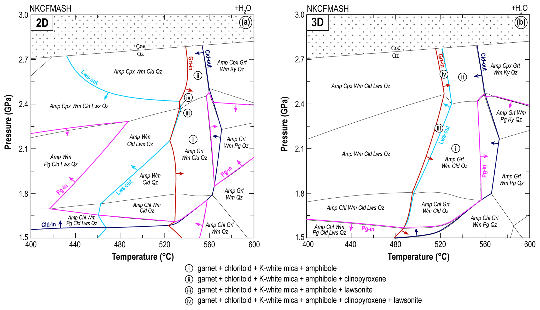
Figure 7Phase diagrams calculated with (a) 2D and (b) 3D local bulk rock compositions, where lawsonite-out, paragonite-in, garnet-in, and chloritoid-out reactions have been highlighted.
5.3 2D vs. 3D investigations: pros and cons
The 2D analysis integrating traditional petrography with quantitative data extracted through the MFA tool allowed the distinction between syn-, pre-, or post-Dp mineral phases based on their orientations to the main Sp foliation. In particular, the long-axis orientations of mineral phases and grain size have been used for this purpose. The main foliation (Sp) and the Sp-1 (within the microlithons) marked by K-white mica, quartz, and chloritoid are visible both in 2D and 3D visualisations.
Conversely, identifying included phases (e.g. chloritoid in garnet) and observing how heterogeneously some mineral phases are distributed (e.g. chloritoid) from the 3D scan is more straightforward than the 2D sample. This might be related to an increased statistical occurrence of different phases in various microstructural positions within the rock volume compared to the thin section. However, it is important to note that (i) grains smaller than the voxel size of the scan, (ii) minerals with similar density, and (iii) crystal intergrowth are hard to identify and classify through the 3D scan. On the contrary, using 2D thin sections integrated with X-ray maps and identifying secondary minerals, internal foliations, and crystal intergrowth or pseudomorphs is easier due to the thin section optical control and chemical constraints on the phase recognition. For both approaches, the scan resolution limits the possibility of detecting small phases that are important to determine the budget of minor but chemically critical elements, such as rutile or ilmenite, affecting the bulk Ti content.
The 2D thin section analysis is straightforward and widely accessible simply because instruments are readily available (e.g. optical microscope and EPMA) and because it has been applied in different geological contexts and case studies. Moreover, 2D techniques allow for rapid data acquisition, making it feasible to analyse more samples within a shorter time frame and at lower costs. Many software and imaging tools for data elaboration (e.g. Petromod, Cossio et al., 2002; XMapTools, Lanari et al., 2014; Q-XRMA, Ortolano et al., 2018) have been recently developed and applied in many recent studies. However, 2D investigations might lead to oversimplification of the complexities of rock volumes by assuming that 2D structures and patterns can be straightforwardly extrapolated to the entire 3D volume of the analysed rock. The choice of the sample sectioning direction can strongly influence the modal proportions if the sample shows strong heterogeneities and anisotropies (i.e. foliated rocks; see Sect. 5.2). For example, minerals with prismatic or lamellar habits may not equally contribute to the modal proportion of the rock if cut perpendicularly or parallel to their long axes.
With 3D µCT scanning and analysis, the occurrence of some mineral phases and microstructures may increase compared to the traditional thin section observations. Textures and structures are well identifiable and constrainable at 360°, considering all possible complexities of multidimensional variables of the rock volume. However, there may be some limitations in the practical extensive use of this technique. For instance, 3D analysis requires significant computational effort and hardware storage to manage rather heavy databases, making their implementation more challenging for researchers with limited resources. Additionally, 3D scans are difficult to implement with the chemical composition of phases (see Corti et al., 2019, as an example of integration of chemical information into µCT scans). Different parameters may also influence the acquisition time of a 3D scan, e.g. the voxel size. Voxel size choices for a reasonable acquisition time are comparable to EPMA X-ray map resolution (e.g. here ∼ 12 µm voxel size vs. 30 µm EPMA X-ray maps resolution). Only integrating EPMA maps with high-resolution thin section scans using Q-XRMA allows an increase in the final resolution of the computed mineral grain boundary map.
In summary, 2D or 3D investigation in metamorphic petrology has advantages and disadvantages, with no major implications and differences when using thermodynamic modelling for P–T estimations. The choice between these two approaches depends on the research question and the available elaboration techniques.
Our understanding of Earth processes, particularly when investigating the tectono-metamorphic history of rocks, is still mostly based on a 2D thin section investigation. High-resolution X-ray µCT, as shown in recent years, has the potential to open multiple new questions to study geologic phenomena from different points of view. Like any other technique, it is important to know its limitations. In conclusion, both 3D and 2D investigations in metamorphic petrology have their strengths and weaknesses. While 3D investigations offer a more comprehensive and realistic representation of metamorphic features, they are computationally intensive and may require specialised tools and expertise. On the other hand, 2D investigations are readily accessible and straightforward, but they risk oversimplifying complex textures. The choice between these approaches should be based on the research question, available resources, and the level of detail needed to address specific scientific issues in metamorphic petrology. Despite differences in the modal distribution, the mismatches in the local bulk rock composition estimates between 2D and 3D are very small, resulting in similar thermodynamic modelled phase fields within error. Thus, our work quantitatively corroborates the reliability of the thin section approach as representative of the sample, still emphasising that 3D analysis can help understand microtextures and their related processes.
The authors declare that all data supporting the findings of this study are available within the article and its Supplement.
The supplement related to this article is available online at: https://doi.org/10.5194/ejm-36-381-2024-supplement.
All authors jointly conceived the study. AP, SN, and FC collected the samples. FC and AP performed the 2D and 3D analysis. All authors discussed and interpreted the obtained results. Scientific validation was from MZ; funding was acquired by AP and AM for µCT analysis and by FC and MZ for EPMA analysis. All authors have read and agreed to the published version of the paper.
The contact author has declared that none of the authors has any competing interests.
Publisher's note: Copernicus Publications remains neutral with regard to jurisdictional claims made in the text, published maps, institutional affiliations, or any other geographical representation in this paper. While Copernicus Publications makes every effort to include appropriate place names, the final responsibility lies with the authors.
We thank Fátima Linares Ordóñez and Encarnación Ruiz Agudo from the Centre for Scientific Instrumentation (University of Granada, Spain) for their support with the lab work and in the data processing. We thank Chiara Groppo for her suggestions and discussions during the manuscript preparation. We thank the two reviewers, Chiara Montemagni and Clément Herviou, for their comments that improved the original manuscript. The handling associate editor, Dejan Prelevic, is thanked for his careful editorial work.
This project has received funding from the 2nd TNA EXCITE call (funded by the European Union's Horizon 2020 research and innovation programme) for the µCT analysis, grant number EXCITE_TNA-C2-2022-072. The results presented here have been developed in the frame of the MIUR project “Dipartimenti di Eccellenza 2017 – Le Geoscienze per la società: risorse e loro evoluzione (work package 3, tasks 3.3 and 3.4)”. The work was partly supported by the Italian Ministry for Universities and Research (MUR) through the project “Dipartimenti di Eccellenza 2023-27”.
This paper was edited by Dejan Prelevic and reviewed by Chiara Montemagni and Clement Herviou.
Avigad, D., Chopin, C., and Le Bayon, R.: Thrusting and Extension in the Southern Dora-Maira Ultra-High-Pressure Massif (Western Alps): View from Below the Coesite-Bearing Unit, J. Geol., 111, 57–70, https://doi.org/10.1086/344664, 2003.
Bonnet, G., Chopin, C., Locatelli, M., Kylander-Clark, A. R., and Hacker, B. R.: Protracted Subduction of the European Hyperextended Margin Revealed by Rutile U-Pb Geochronology Across the Dora-Maira Massif (Western Alps), Tectonics, 41, e2021TC007170, https://doi.org/10.1029/2021TC007170, 2022.
Brown, M.: The contribution of metamorphic petrology to understanding lithosphere evolution and geodynamics, Geosci. Front., 5, 553–569, https://doi.org/10.1016/j.gsf.2014.02.005, 2014.
Caddick, M. J. and Thompson, A. B.: Quantifying the tectono-metamorphic evolution of pelitic rocks from a wide range of tectonic settings: mineral compositions in equilibrium, Contrib. Mineral. Petr., 156, 177–195, https://doi.org/10.1007/s00410-008-0280-6, 2008.
Caso, F.: Quantitative combined multiscale structural and minero-chemical analysis to unravel the tectono-metamorphic evolution of cordierite-migmatite gneiss from the Valpelline Unit (Dent-Blanche Nappe, Western Italian Alps, Valle d'Aosta), Rend. Online Soc. Geol. It., 60, 2–10, https://doi.org/10.3301/ROL.2023.20, 2023.
Caso, F., Piloni, C. B., Filippi, M., Pezzotta, A., Fazio, E., Visalli, R., Ortolano, G., Roda, M., and Zucali, M.: Combining traditional and quantitative multiscale structural analysis to reconstruct the tectono-metamorphic evolution of migmatitic basements: the case of the Valpelline Series, Dent-Blanche Tectonic System, Western Alps, J. Struct. Geol., 182, 105099, https://doi.org/10.1016/j.jsg.2024.105099, 2024.
Chopin, C., Henry, C., and Michard, A.: Geology and petrology of the coesite-bearing terrain, Dora Maira massif, Western Alps, Eur. J. Mineral., 3, 263–291, https://doi.org/10.1127/ejm/3/2/0263, 1991.
Cnudde, V. and Boone, M. N.: High-resolution X-ray computed tomography in geosciences: A review of the current technology and applications, Earth Sci. Rev., 123, 1–17, https://doi.org/10.1016/j.earscirev.2013.04.003, 2013.
Connolly, J. A. D.: The geodynamic equation of state: what and how, Geochem. Geophy. Geosy., 10, Q10014, https://doi.org/10.1029/2009GC002540, 2009.
Corti, L., Zucali, M., Visalli, R., Mancini, L., and Mohammad, S.: Integrating X-ray computed tomography with chemical imaging to quantify mineral re-crystallization from granulite to eclogite metamorphism in the Western Italian Alps (Sesia-Lanzo Zone), Front. Earth Sci., 7, 327, https://doi.org/10.3389/feart .2019.00327, 2019.
Cossio, R., Borghi, A., and Ruffini, R.: Quantitative modal determination of geological samples based on X-ray multielemental map acquisition, Microsc. Microanal., 8, 139–149, https://doi.org/10.1017/S1431927601020062, 2002.
Forshaw, J. B. and Pattison, D. R. M.: Major-element geochemistry of pelites, Geology, 51, 39–43, https://doi.org/10.1130/G50542.1, 2023a.
Forshaw, J. B. and Pattison, D. R.: Bulk compositional influence on diverse metapelitic mineral assemblages in the Whetstone Lake area, Ontario, J. Petrol., 64, egad071, https://doi.org/10.1093/petrology/egad071, 2023b.
Fuhrman, M. L. and Lindsley, D. H.: Ternary-Feldspar Modeling and Thermometry, Am. Mineral., 73, 201–215, 1988.
Gaidies, F., Mccarron, T., Simpson, A. D., Easton, R. M., Glorie, S., Putlitz, B., and Trebus, K.: Polymetamorphism during the Grenvillian Orogeny in SE Ontario: Results from trace element mapping, in situ geochronology, and diffusion geospeedometry, J. Metamorph. Geol., 42, 35–61, https://doi.org/10.1111/jmg.12745, 2023.
George, F. and Gaidies, F.: Characterisation of a garnet population from the Sikkim Himalaya: Insights into the rates and mechanisms of porphyroblast crystallisation, Contrib. Mineral. Petr., 172, 57, https://doi.org/10.1007/s00410-017-1372-y, 2017.
Giamas, V., Koutsovitis, P., Sideridis, A., Turberg, P., Grammatikopoulos, T. A., Petrounias, P., Giannakopoulou P. P., Koukouzas, N., and Hatzipanagiotou, K.: Effectiveness of X-ray micro-CT applications upon mafic and ultramafic ophiolitic rocks, Micron, 158, 103292, https://doi.org/10.1016/j.micron.2022.103292, 2022.
Giuntoli, F., Viola, G., and Sørensen, B. E.: Deformation mechanisms of blueschist facies continental metasediments may offer insights into deep episodic tremor and slow slip events, J. Geophys. Res.-Sol. Ea., 127, e2022JB024265, https://doi.org/10.1029/2022JB024265, 2022.
Green, E. C. R., Holland, T. J. B., and Powell, R.: An order-disorder model for omphacitic pyroxenes in the system jadeite-diopside-hedenbergite-acmite, with applications to eclogite rocks, Am. Mineral., 92, 1181–1189, https://doi.org/10.2138/am.2007.2401, 2007.
Green, E. C. R., White, R. W., Diener, J. F. A., Powell, R., Holland, T. J. B., and Palin, R. M.: Activity–composition relations for the calculation of partial melting equilibria in metabasic rocks, J. Metamorph. Geol., 34, 845–869, https://doi.org/10.1111/jmg.12211, 2016.
Groppo, C. and Castelli, D.: Prograde P–T Evolution of a Lawsonite Eclogite from the Monviso Meta-ophiolite (Western Alps): Dehydration and Redox Reactions during Subduction of Oceanic FeTi-oxide Gabbro, J. Petrol., 51, 2489–2514, https://doi.org/10.1093/petrology/egq065, 2010.
Groppo, C., Ferrando, S., Gilio, M., Botta, S., Nosenzo, F., Balestro, G., Festa, A., and Rolfo, F.: What's in the sandwich? New P–T constraints for the (U)HP nappe stack of southern Dora-Maira Massif (Western Alps), Eur. J. Mineral., 31, 665–683, https://doi.org/10.1127/ejm/2019/0031-2860, 2019.
Hartmeier, P., Lanari, P., Forshaw, J. B., and Markmann, T. A.: Tracking garnet dissolution kinetics in 3D using deep learning grain shape classification, J. Petrol., 65, egae005, https://doi.org/10.1093/petrology/egae005, 2024.
Heilbronner, R. and Bruhn, D.: The influence of three-dimensional grain size distributions on the rheology of polyphase rocks, J. Struct. Geol., 20, 695–705, https://doi.org/10.1016/S0191-8141(98)00010-8, 1998.
Herron, M. M.: Geochemical classification of terrigenous sands and shales from core or log data, J. Sediment. Petrol., 58, 820–829, https://doi.org/10.1306/212F8E77-2B24-11D7-8648000102C1865D, 1988.
Herviou, C., Agard, P., Verlaguet, A., Gyomlai, T., Bonnet, G., Mendes, K., and Plunder, A.: Fractal distribution of subduction-related crack-seal veins (Schistes Lustrés, W. Alps): Implications for fluid flow and rupture processes at the downdip end of the seismogenic zone, J. Geophys. Res.-Sol. Earth, 128, e2022JB026317, https://doi.org/10.1029/2022JB026317, 2023.
Holder, R. M., Viete, D. R., Brown, M., and Johnson, T. E.: Metamorphism and the evolution of plate tectonics, Nature, 572, 378–381, https://doi.org/10.1038/s41586-019-1462-2, 2019.
Holland, T. J. B. and Powell, R.: An internally-consistent thermodynamic dataset for phases of petrological interest, J. Metamorph. Geol., 16, 309–344, https://doi.org/10.1111/j.1525-1314.1998.00140.x, 1998.
Holland, T. J. B. and Powell, R.: An improved and extended internally consistent thermodynamic dataset for phases of petrological interest, involving a new equation of state for solids, J. Metamorph. Geol., 29, 333–383, https://doi.org/10.1111/j.1525-1314.2010.00923.x, 2011.
Lanari, P. and Duesterhoeft, E.: Modeling metamorphic rocks using equilibrium thermodynamics and internally consistent databases: Past achievements, problems and perspectives, J. Petrol., 60, 19–56, https://doi.org/10.1093/petrology/egy105, 2019.
Lanari, P. and Engi, M.: Local Bulk Composition Effects on Metamorphic Mineral Assemblages, Rew. Mineral. Geochem., 83, 55–102, https://doi.org/10.2138/rmg.2017.83.3, 2017.
Lanari, P., Vidal, O., De Andrade, V., Dubacq, B., Lewin, E., Grosch, E. G., and Schwartz, S.: XMapTools: A MATLAB©-based program for electron microprobe X-ray image processing and geothermobarometry, Comput. Geosci., 62, 227–240, https://doi.org/10.1016/j.cageo.2013.08.010, 2014.
Macente, A., Fusseis, F., Menegon, L., Xiao, X., and John, T.: The strain-dependent spatial evolution of garnet in a high-P ductile shear zone from the Western Gneiss Region (Norway): a synchrotron X-ray microtomography study, J. Metamorph. Geol., 35, 565–583 https://doi.org/10.1111/jmg.12245, 2017.
Maire, E. and Withers, P. J.: Quantitative X-ray tomography, Int. Mater. Rev., 59, 1–43, https://doi.org/10.1179/1743280413Y.0000000023, 2014.
Manzotti, P., Schiavi, F., Nosenzo, F., Pitra, P., and Ballevre, M.: A journey towards the forbidden zone: A new, cold, UHP unit in the Dora-Maira Massif (Western Alps), Contrib. Mineral. Petr., 177, 59, https://doi.org/10.1007/s00410-022-01923-8, 2022.
Michard, A., Henry, C., and Chopin, C.: Compression versus extension in the exhumation of the Dora-Maira coesite-bearing unit, Western Alps, Italy, Tectonophysics, 221, 173–193, https://doi.org/10.1016/0040-1951(93)90331-D, 1993.
Michard, A., Schmid, S. M., Lahfid, A., Ballèvre, M., Manzotti, P., Chopin, C., Iaccarino, S., and Dana, D.: The Maira-Sampeyre and Val Grana Allochthons (south Western Alps): review and new data on the tectonometamorphic evolution of the Briançonnais distal margin, Swiss J. Geosci., 115, 1–43, https://doi.org/10.1186/s00015-022-00419-8, 2022.
Montemagni, C., Carosi, R., Fusi, N., Iaccarino, S., Montomoli, C., Villa, I. M., and Zanchetta, S.: Three-dimensional vorticity and time-constrained evolution of the Main Central Thrust zone, Garhwal Himalaya (NW India), Terra Nova, 32, 215–224, https://doi.org/10.1111/ter.12450, 2020.
Nerone, S., Groppo, C., and Rolfo, F.: Equilibrium and kinetic approaches to understand the occurrence of the uncommon chloritoid + biotite assemblage, Eur. J. Mineral., 35, 305–320, https://doi.org/10.5194/ejm-35-305-2023, 2023.
Nerone, S., Petroccia, A., Caso, F., Dana, D., and Maffeis, A.: Assessing the importance of H2O content in the tectono-metamorphic evolution of shear zones: a case study from the Dora-Maira Massif (Western Alps), J. Metamorph. Geol., 42, 171–196, https://doi.org/10.1111/jmg.12750, 2024.
Ortolano, G., Visalli, R., Gaston, G., and Cirrincione, R.: Quantitative X-ray Map Analyser (Q-XRMA): A new GIS-based statistical approach to Mineral Image Analysis, Comput. Geosci., 115, 56–65, https://doi.org/10.1016/j.cageo.2018.03.001, 2018.
Palin, R. M., Weller, O. M., Waters, D. J., and Dyck, B.: Quantifying geological uncertainty in metamorphic phase equilibria modelling; a Monte Carlo assessment and implications for tectonic interpretations, Geosci. Front., 7, 591–607, https://doi.org/10.1016/j.gsf.2015.08.005, 2016.
Passchier, C. W. and Trouw, R. A. J.: Microtectonics, 2nd Edn., Springer, Berlin, Heidelberg, 366 pp., https://doi.org/10.1007/3-540-29359-0, 2005.
Petri, B., Almqvist, B. S., and Pistone, M.: 3D rock fabric analysis using micro-tomography: An introduction to the open-source TomoFab MATLAB code, Comput. Geosci., 138, 104444, https://doi.org/10.1016/j.cageo.2020.104444, 2020.
Petroccia, A. and Iaccarino, S.: Metaconglomerate in the Pinerolo Unit (Dora Maira Massif, Western Alps): a key outcrop for Alpine geology and training structural geologists, Int. J. Earth Sci., 111, 317–319, https://doi.org/10.1007/s00531-021-02087-9, 2022.
Plunder, A. Agard, P. Dubacq, B. Chopin, C., and Bellanger, M.: How continuous and precise is the record of P–T paths? Insights from combined thermobarometry and thermodynamic modelling into subduction dynamics (Schistes Lustrés, W. Alps), J. Metamorph. Geol., 30, 323–346, https://doi.org/10.1111/j.1525-1314.2011.00969.x, 2012.
Sharma, J. J., Naik, A., Pant, N., Arora, D., Pandey, M., and Singh, P.: Estimation of effective bulk composition – critical appraisal and a scanning electron microscope based approach, Geol. J., 56, 2950–2962, https://doi.org/10.1002/gj.4077, 2021.
Spear, F. S., Pattison, D. R. M., and Cheney, J. T.: The metamorphosis of metamorphic petrology, in: The Web of Geological Sciences: Advances, Impacts, and Interactions II, edited by: Bickford, M. E., Geol. Soc. Am. Spec. Paper, 523 pp., https://doi.org/10.1130/2016.2523(02), 2016.
Sun, W., Wang, L., and Wang, Y.: Mechanical properties of rock materials with related to mineralogical characteristics and grain size through experimental investigation: a comprehensive review, Front. Struct. Civ. Eng., 11, 322–328, https://doi.org/10.1007/s11709-017-0387-9, 2017.
Taylor, R.: The future of automated mineralogy in geoscience, Wiley Analytical Science Magazine, https://analyticalscience.wiley.com/content/article-do/future-automated-mineralogy-geoscience (last access: 26 April 2024), 2022.
Tinkham, D. K. and Ghent, E. D.: Estimating PT conditions of garnet growth with isochemical phase-diagram sections and the problem of effective bulk-composition, Can. Mineral., 43, 35–50, https://doi.org/10.2113/gscanmin.43.1.35, 2005.
Turner, F. J. and Weiss, L. E.: Structural analysis of metamorphic tectonites, MacGraw-Hill, 545 pp., ISBN 978-0070655744, 1963.
Vernon, R. H.: Relationships between microstructures and metamorphic assemblages, Tectonophysics, 39, 439–452, https://doi.org/10.1016/0040-1951(77)90108-1, 1977.
Vialon, P.: Étude géologique du Massif Cristallin Dora-Maira (Alpes Cottiennes internes-Italie), PhD thesis, University of Grenoble, Grenoble, https://tel.archives-ouvertes.fr/tel-00723197 (last access: 26 April 2024), 1966.
Visalli, R., Ortolano, G., Godard, G., and Cirrincione, R.: Micro-Fabric Analyzer (MFA): A New Semiautomated ArcGIS-Based Edge Detector for Quantitative Microstructural Analysis of Rock Thin-Sections, ISPRS Int. J. Geo-Inf., 10, 51, https://doi.org/10.3390/ijgi10020051, 2021.
Warr, L. N.: IMA–CNMNC approved mineral symbols, Mineral. Mag., 85, 291–320, https://doi.org/10.1180/mgm.2021.43, 2021.
White, R. W., Powell, R., and Johnson, T. E.: The effect of Mn on mineral stability in meta-pelites revisited: new a-x relations for manganese-bearing minerals, J. Metamorph. Geol., 32, 809–828, https://doi.org/10.1111/jmg.12095, 2014.
Zucali, M., Voltolini, M., Ouladdiaf, B., Mancini, L., and Chateigner, D.: The 3D quantitative lattice and shape preferred orientation of a mylonitised metagranite from Monte Rosa (Western Alps): Combining neutron diffraction texture analysis and synchrotron X-ray microtomography, J. Struct. Geol., 63, 91–105, https://doi.org/10.1016/j.jsg.2014.02.011, 2014.
- Abstract
- Introduction
- Methods
- Petrochemistry and microstructures
- Two-dimensional vs. three-dimensional phase modal distribution and local bulk rock composition
- Discussion
- Conclusions
- Data availability
- Author contributions
- Competing interests
- Disclaimer
- Acknowledgements
- Financial support
- Review statement
- References
- Supplement