the Creative Commons Attribution 4.0 License.
the Creative Commons Attribution 4.0 License.
 | 04 Sep 2023
The effect of chemical variability and weathering on Raman spectra of enargite and fahlore
Khulan Berkh
Juraj Majzlan
Jeannet A. Meima
Jakub Plášil
Dieter Rammlmair
Enargite (Cu3AsS4) and tennantite (Cu12As4S13) are typical As-bearing sulfides in intermediate- and high-sulfidation epithermal deposits. Trace and major element variations in enargite and tennantite and their substitution mechanisms are widely described. However, Raman spectra of the minerals with correlative quantitative chemical information are rarely documented, especially for enargite. Therefore, comparative electron and μ-Raman microprobe analyses were performed on enargite and fahlore grains. These spectra can be used in the industrial detection and subsequent removal of As-bearing sulfides prior to ore beneficiation in order to diminish the environmental impact of the metallurgical technologies.
A simple Sb5+–As5+ substitution in enargite was confirmed by Raman analyses. Similarly, a complete solid solution series from tetrahedrite to tennantite (i.e., Sb3+–As3+ substitution) can be correlated with a gradual evolution in their Raman spectra. In turn, Te4+ occupies the As3+ and Sb3+ sites in fahlore by the coupled substitution Te4+ + Cu+ → (As, Sb)3+ + (Cu, Fe, Zn)2+. Accordingly, Raman bands of goldfieldite (Te-rich member) are strongly broadened compared with those of tetrahedrite and tennantite.
A secondary phase with high porosity and a fibrous or wormlike texture was found in enargite in a weathered sample. The chemical composition, Raman spectrum, and X-ray diffraction signature of the secondary phase resemble tennantite. A gradual transformation of the primary enargite into this secondary phase was visualized by comparative electron and Raman microprobe mapping.
- Article
(13511 KB) - Full-text XML
-
Supplement
(447 KB) - BibTeX
- EndNote


1.1 Arsenic problem
Porphyry–copper deposits are a group of ore deposits located in active continental margins. They are often overprinted by high-sulfidation epithermal mineralization with Cu–As minerals such as enargite (Cu3AsS4) and tennantite (Cu12As4S13) (Sillitoe, 2010). A number of porphyry–copper deposits and camps is concentrated in Chile, making this country the largest copper producer in the world. However, some of the copper mines in Chile increasingly produce copper concentrates with an elevated arsenic concentration.
Since arsenic and its compounds are detrimental to the environment, the As-bearing fumes generated during the smelting process must be cleaned before they are released into the atmosphere. However, the stringent requirements for the gas purification plants make the beneficiation of high-As concentrates uneconomical. Thus, prior to smelting, the arsenic content must be reduced as much as reasonably possible, usually to less than 0.3 wt % (Wilkomirsky et al., 2020). Good progress has been made in recent years in pre-treatment process technologies such as selective flotation, leaching, and partial roasting of enargite and tennantite (Long et al., 2012, 2014; Tayebi-Khorami et al., 2017, 2018; Li et al., 2019; Wilkomirsky et al., 2020; Chen et al., 2021). Nevertheless, the processes are still too complex and costly to achieve the desired arsenic levels. Reducing arsenic content at an earlier stage, e.g., by separating As-rich bulk material from As-poor material, would help to decrease the volume of material to be treated, lower the treatment costs, and protect the environment.
For this reason, the purpose of this work is to employ Raman spectroscopy as a tool to differentiate the As-rich member tennantite from the Sb-rich tetrahedrite that is less detrimental to the environment than tennantite. If successful, such a tool could be applied on a commercial scale for arsenic reduction pre-treatment. For the same reason, Raman spectroscopy was applied to enargite, and the results were correlated with its chemical composition. Both fresh and weathered enargite was investigated because oxidative weathering modifies surface reactivity and its hydrophobic or hydrophilic properties, thus affecting the flotation efficiency.
Mild surface oxidation can enhance the floatability of the sulfides due to the formation of hydrophobic oxidation products such as metal-deficient coatings with elemental sulfur or polysulfides (Rumball and Richmond, 1996). Advanced surface oxidation, in turn, reduces the floatability by formation of metal oxide and hydroxide layers and prevents the adsorption of collectors onto the mineral surface (Senior and Trahar, 1991). The oxidation products can cover and encrust both target and gangue minerals and diminish the flotation selectivity between those minerals (Rumball and Richmond, 1996). Enargite weathering under natural conditions and the associated arsenic release into the environment are slow processes. The comminution of the ores significantly accelerates the release, making As-containing mine waste a labile, hazardous source of arsenic. Therefore, the last objective of our study is the investigation of the secondary products of enargite weathering. They play a decisive role in the release or retainment of arsenic in the waste form.
1.2 Enargite properties relevant to the Raman spectroscopy study
Enargite is a high-temperature orthorhombic (space group Pmn21) modification of Cu3AsS4, with Cu as Cu+ and As as As5+ (Li et al., 1994). The crystal structure can be derived from the wurtzite (ZnS) structure, with copper and arsenic atoms replacing zinc in an ordered fashion. Both elements are tetrahedrally coordinated by sulfur (Pauling and Weinbaum, 1934). The As–S bonds in sulfides are strongly covalent (O'Day, 2006), with a mean interatomic distance of 2.21 Å (Karanovi et al., 2002) or 2.25 Å (Pauling, 1970).
A group theory treatment of the lattice vibrations in enargite predicts a total of 45 Raman active modes: 13A1 + 10A2 + 9B1 + 13B2. Just as in wurtzite, the electrostatic forces dominate over the anisotropy of the short-range forces, causing the Raman bands to be split into transverse optic (TO) and longitudinal optic (LO) modes. Accordingly, the two strong bands at 337 and 382 cm−1 are assigned to the LO and TO modes. Other very weak bands at 133, 151, and 170 cm−1 most probably represent the lattice modes (Mernagh and Trudu, 1993).
The low-temperature polymorph of enargite is luzonite that forms a complete solid solution with famatinite (Cu3SbS4). In enargite, however, the Sb incorporation is limited to 11 at. % at 600 ∘C and much less at lower temperatures (Pósfai and Buseck, 1998). An increasing Sb content results in the expansion of the unit cell (Pfitzner and Bernert, 2004).
1.3 Fahlore properties relevant to the Raman spectroscopy study
Tennantite and tetrahedrite form a cubic (space group I-43m) solid solution of sulfosalts with a general name fahlore and a general chemical formula (Cu,Ag)10(Zn,Fe,Cu)2(As,Sb)4S13, with Cu as Cu+ and Cu2+ and As as As3+ (Takéuchi and Sadanaga, 1969; Li et al., 1994). The crystal chemistry of the minerals of the tetrahedrite group has recently been discussed in detail by Biagioni et al. (2020). The structural formula of these minerals is M(2)A6M(1)(B4C2)X(3)D4S(1)Y12S(2)Z, where A = Cu+, Ag+, □ (vacancy), and (Ag6)4+ clusters; B = Cu+ and Ag+; C = Zn2+, Fe2+, Hg2+, and Cd2+; D = Sb3+, As3+, Bi3+, and Te4+; Y = S2− and Se2−; and Z = S2−, Se2−, and □.
The vibrations of the DY3 pyramids are responsible for the characteristic spectral bands of the solid solution series. There are four vibrational modes, including two stretching frequencies ν1 and ν3 and two bending frequencies ν2 and ν4. All four modes are IR and Raman active and are ordered in their frequencies as . There is an overlap of ν1 with ν3 and ν2 with ν4, resulting in two main broad bands (Nakamoto, 1997). The effect of As–Sb substitution in the Raman spectra of tetrahedrite–tennantite solid solution was investigated by Kharbish et al. (2007) and Apopei et al. (2017). The As–S interatomic distance in tennantite is 2.25 Å (Makovicky et al., 2005), whereas the Sb–S distance in tetrahedrite is 2.43 Å (Pfitzner et al., 1997).
1.4 Enargite oxidation
There is voluminous literature on ore deposits that contain enargite, with a focus on their genesis, ore mineralogy, and hydrothermal alterations. On the other hand, weathering of enargite has not been studied in such detail as it is not of prime interest to economic geologists. There are, however, many experimental studies on the oxidative dissolution of enargite from the view of mineral processing, systematically summarized by Lattanzi et al. (2008). We focus especially on the studies carried out under neutral and acidic conditions because oxidation of enargite is an acid-generating process, and acid mine drainage is a serious issue for As-containing mine wastes (Dold, 2008).
Da Pelo (1998) observed antlerite Cu3(SO4)(OH)4 along cracks and in cavities of enargite after being kept for a month at 80 ∘C and 80 % relative humidity. Rossi et al. (2001) detected a thin layer covering the surface of a natural specimen exposed to the ambient air for a longer time. The uppermost part of the layer (∼ 0.5 nm) was enriched in arsenic, with sulfur as S2−, S0, and S6+. A layer beneath was strongly enriched in Cu and depleted in S. Viñals et al. (2003) found evidence of As–O bonds and polysulfide species but no sulfate sulfur in untreated natural samples. They concluded that enargite has a surface layer containing Cu+ and arsenic-deficient sulfoarsenide with monosulfide and polysulfide components. Experiments with water showed that there is no interaction with water (Lattanzi et al., 2008). However, a mechanochemical treatment such as grinding causes chemical activation and strongly speeds up oxidation in air. Arsenic that was initially bound to sulfides in an enargite-bearing copper ore was converted to oxide by dry grinding using ball milling and could then easily be dissolved in water or alkaline solution (Ishihara et al., 2019).
The dissolution rate of enargite in ferric sulfate/sulfuric acid solutions strongly depends on the Fe3+ concentration and depends less on the H+ concentration (Dutrizac and Macdonald, 1972). Native sulfur was the only solid reaction product the authors found, subsequently partially oxidized to sulfate. Davis et al. (1992) showed that enargite dissolves very slowly but almost completely under oxidizing conditions at pH 2.0. Significant oxidation/dissolution only occurs in the presence of a strong oxidizing agent. In an electrochemical study at pH 1, Ásbjörnsson et al. (2004) observed the formation of native sulfur on the enargite surface. The finding was also confirmed by in situ Raman spectroscopy. Furthermore, Cu(II) associated with sulfate and As(III)–O species were found at the surface. The electrochemical reduction in enargite was interpreted with the formation of H2S, AsH3, and Cu0. Elsener et al. (2007) studied oxidative dissolution of enargite in acidic solutions with 0.025 M Fe3+ to simulate abiotic acid mine drainage environments. The authors observed multiple layers on enargite. A thin metal-deficient layer formed at the surface, showing that copper and arsenic initially dissolve into solution. Below this layer, enargite is slightly depleted in copper and enriched in sulfur. A formation of polysulfide instead of elemental sulfur at the enargite surface is assumed in contrast to Dutrizac and MacDonald (1972). Sasaki et al. (2010) oxidized enargite in H2O2 with O2 gas at pH 2 and 5. Native sulfur was formed especially at pH 2. Plackowski (2014) studied the surface oxidation and hydrophobicity of a natural enargite sample. At a pH value of 4, a metal-deficient sulfide surface layer with elemental sulfur was formed.
In summary, the dominant process during enargite oxidation under acidic conditions is copper dissolution, forming a copper-depleted layer with polysulfide that oxidizes to elemental sulfur and further to sulfate. Additionally, Cu(II) and As–O species were shown to be present (Ásbjörnsson et al., 2004; Herreros et al., 2002; Padilla et al., 2005). Dissolution rates are higher in the presence of Fe3+ (Davis et al., 1992; Dutrizac and MacDonald, 1972). The release of copper is faster than that of arsenic (Dutrizac and MacDonald, 1972; Ásbjörnsson et al., 2004).
2.1 Materials
Chilean copper concentrates from a porphyry Cu–Mo deposit that is overprinted by a high-sulfidation mineralization containing enargite and tennantite were investigated. Two different concentrates were available for this study. One was fresh and the other was strongly weathered as the concentrate was kept directly after froth flotation (probably wet at this point) in an exogenous environment for presumably more than 10 years as a retain sample. The fresh concentrate is used to analyze the chemical diversity of enargite and fahlore and their Raman spectra. The weathered concentrate is used to describe the weathering behavior of enargite. The concentrates were embedded in epoxy resin, ground with a diamond pulley wheel (45 and 15 µm), and polished with diamond paste (3 µm) on cloth. The resulting polished sections were analyzed with an electron probe micro-analyzer (EPMA) and a Raman microprobe. Additionally, the weathered concentrate was deagglomerated with distilled water and sieved with a mesh size of 250 µm. Then, the larger enargite grains were handpicked from the bulk coarse fraction under a binocular microscope, washed with distilled water, and dried. The grains were attached to a glass slide with double-sided tape and scanned with the Raman microprobe using an automatic focus track mode. Afterwards, the grains were placed in a glass tube and measured using an X-ray diffractometer (XRD).
2.2 Electron probe micro-analyzer (EPMA)
The chemical composition of sulfides was determined by a field-emission gun electron microprobe JEOL JXA-8530 F, using wavelength-dispersive spectrometry. The point measurements were acquired with a focused beam of 0.5 µm in size, operating voltage of 25 kV, and beam current of 50 nA. The measured elements and their specifications (X-ray line, acquisition time, reference material used for calibration, and calculated detection limit) were S (Kα, 10 s, PET, pyrite, 107 ppm), Fe (Kα, 10 s, LIFL, pyrite, 66 ppm), Cu (Kα, 10 s, LIFL, chalcocite, 80 ppm), Zn (Kα, 40 s, LIFL, sphalerite, 46 ppm), As (Lα, 40 s, TAP, arsenopyrite, 119 ppm), Ag (Lα, 60 s, PETH, Ag metal, 110 ppm), Cd (Lα, 35 s, PETH, synthetic CdTe, 157 ppm), Sb (Lα, 40 s, PETH, stibnite, 75 ppm), Te (Lα, 40 s, PETH, synthetic CdTe, 55 ppm), Hg (Lα, 40 s, PETH, cinnabar, 132 ppm), and Pb (Mα, 40 s, PETH, galena, 116 ppm). For the semi-quantitative element distribution maps, the same operating conditions were applied. The beam size and dwell time were here 0.5 µm and 1 s, respectively.
2.3 Laser Raman microprobe
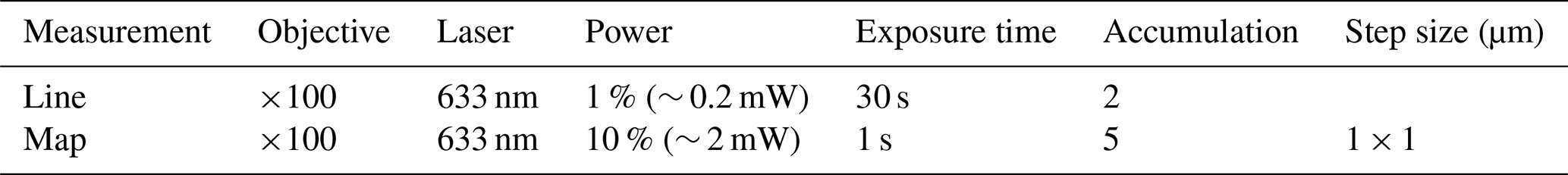
Raman spectra were recorded with a Renishaw inVia Qontor confocal μ-Raman system attached to a Leica DM2700 microscope. For the polished sample, an N plan 100× objective lens with a 0.85 numerical aperture and 0.27 mm working distance was used to collect the scattered radiation from the sample. For the rough surfaces of the handpicked enargite grains, an automatic focus track mode and an N plan 20× objective lens with a 0.40 numerical aperture and 1.15 mm working distance were applied. A HeNe laser with a wavelength of 633 nm was used as the excitation source. Unpolarized spectra were recorded by the Renishaw Centrus 1873H8 detector with a charge-coupled device (CCD) array of 1040 × 256 pixels using a 1800 L mm−1 grating. The spectral resolution was 0.82 cm−1. Different settings depending on the measurement type were applied and are listed in Table 1.
The instrument was calibrated by automatic alignment procedures of the software WiRE, including laser spot correction, CCD area, and slit alignments. The correctness of the calibration was verified with the 520.5 cm−1 band of an unprocessed (111) crystalline silicon wafer from First Sensor. The verification is adequate because all Raman modes of the analyzed minerals occur between the laser line and the 520.5 cm−1 band of the standard silicon wafer. Raw spectra were processed by the WiRE software. The background was subtracted, and spikes caused by cosmic ray events were filtered out. The position, intensity, and full width at half maximum (FWHM) of the Raman bands were determined by the curve fit function of the software. A combined Gaussian–Lorentzian band shape was fitted to the data to minimize the chi-squared (χ2) value that measures the goodness of fit.
2.4 X-ray diffraction
The qualitative mineral composition of the handpicked weathered enargite grains was determined by powder X-ray diffraction. The instrument used was the PANalytical MPD Pro XRD, employing Cu Kα radiation and the scientific X'Cellerator as the second detector, adapted for rock analyses.
A single-crystal X-ray diffractometer Rigaku SuperNova was employed to collect both single-crystal and powder (pseudo-Gandolfi) X-ray diffraction data at room temperature. The diffractometer is equipped with the Atlas S2 CCD detector and utilizes a microfocus Mo Kα source. Data were processed using CrysAlisPro version 1.171.39.46 (Rigaku Oxford Diffraction, 2019). A Gandolfi-like motion on the ϕ and ω axes was used to randomize the sample to acquire powderlike X-ray diffraction data.
3.1 Chemical composition of the fresh enargite and the corresponding Raman spectra
Enargite grains from the fresh copper concentrates were randomly selected and analyzed by EPMA (n=122). The measurement points were set in the center of the grains. The results are listed in Table S1 in the Supplement and are visualized in Fig. 1.
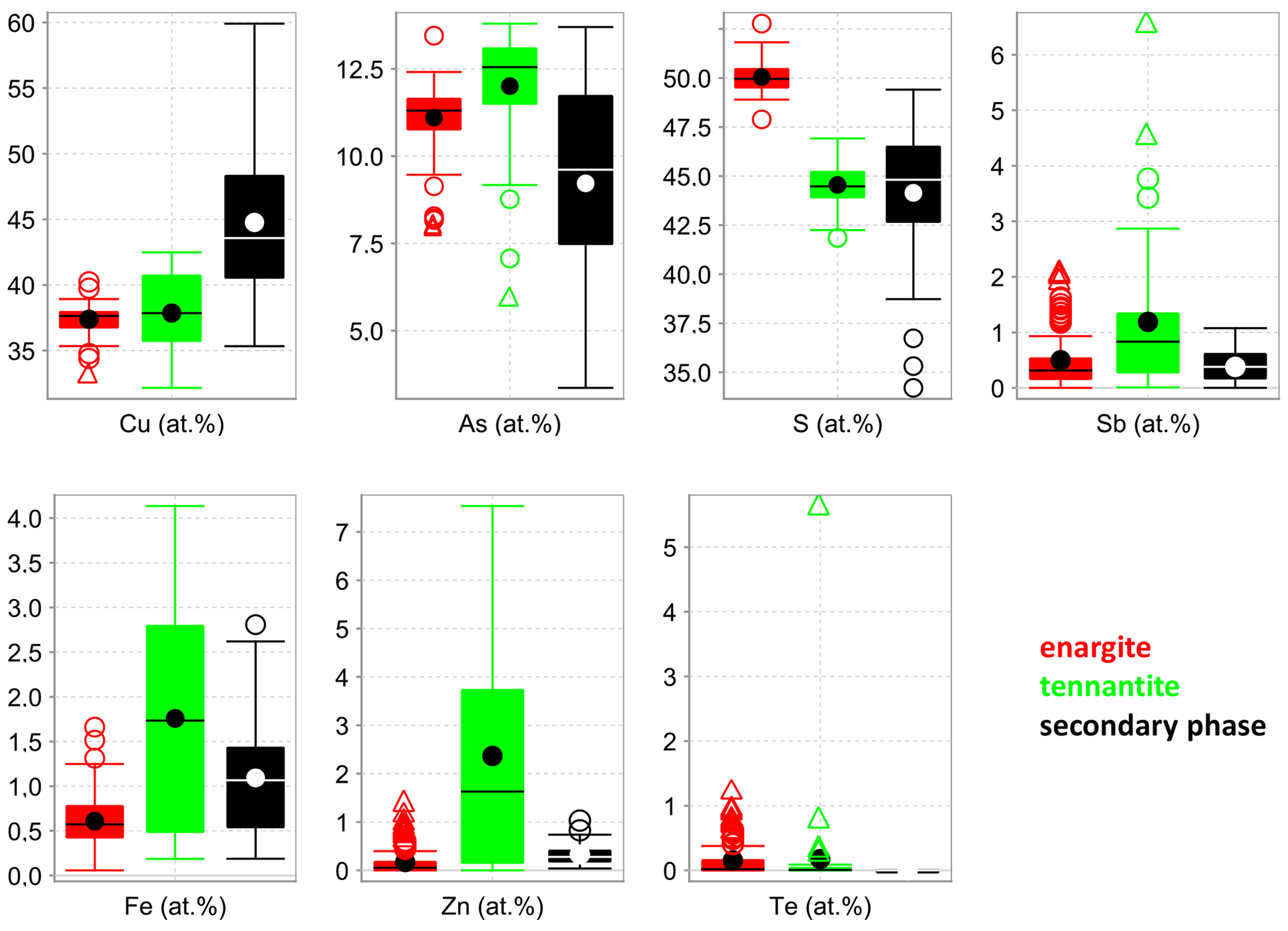
Figure 1Box-and-whisker diagrams for the elements analyzed in the fresh enargite and tennantite, as well as the secondary phase in weathered enargite measured with EPMA.
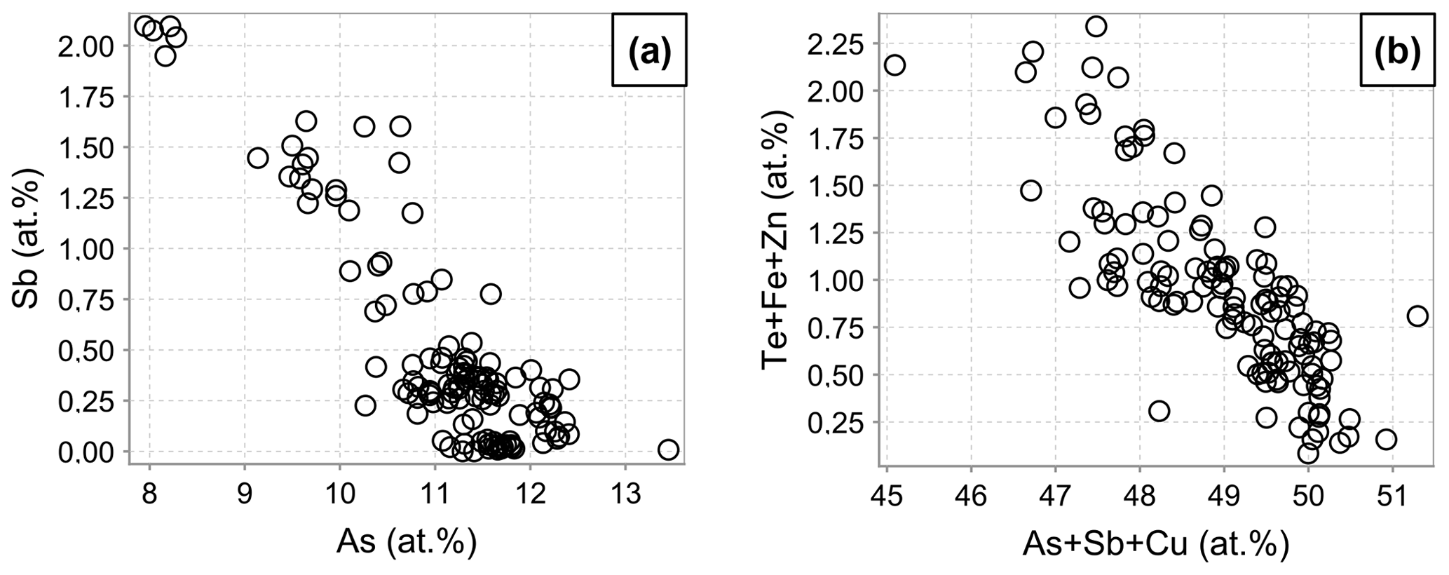
The medians of the major element concentrations in the fresh enargite (EPMA analyses, Fig. 1) are 37.6 at. % Cu, 11.3 at. % As, and 50.0 at. % S. These data give a cation to anion ratio of 0.98 : 1.00, suggesting stoichiometric enargite within the error of the measurement. The medians of the minor elements are 0.3 at. % Sb, 0.6 at. % Fe, and 0.1 at. % Zn. Further minor and trace elements are Te, Ag, Cd, and Pb, with concentrations below 1.2 at. %, 0.1 at. %, 0.1 at. %, and 0.1 at. %, respectively. Figure 2 shows correlation diagrams based on individual point analyses. Antimony concentrations correlate negatively to those of As with a coefficient of determination R2=0.76, indicating a simple homovalent Sb–As substitution. Tellurium, Fe, and Zn concentrations negatively correlate with As, Sb, and Cu (R2=0.65), which hints at a coupled substitution of Te4+ with Fe2+ or Zn2+ for Cu1+ and As5+ to maintain the charge balance. Apart from this, no other correlations were observed.
One of the enargite grains was mapped by EPMA to document the different substitution mechanisms within a single grain. The selection of the grain was based on elevated Sb concentrations and grain-scale heterogeneity. The element distribution maps are shown in Fig. 3 in addition to the back-scattered electron (BSE) and reflected-light (RL) images. In the element distribution maps, the green anomalies (false colors) in the S and Zn map present tennantite veinlets, whereas the red anomalies in the Zn and Fe map present inclusions of sphalerite and pyrite, respectively. The element distribution maps reflect the element correlations obtained by the point analyses shown in Fig. 2. There is a negative As–Sb and Te–(Cu,As) correlation and a positive Te–Zn correlation.
Raman spectroscopy mapping was carried out on the same grain, as shown in Fig. 3. After collecting the spectra, K-means cluster analysis was performed with the WiRE software. The obtained cluster map is shown in Fig. 3j. The patterns discerned in the cluster correlate strongly with the Sb distribution map. The green cluster is located where the highest Sb concentration exists, while the black cluster occurs where the lowest Sb concentration is present. The blue and cyan clusters represent areas of moderate Sb concentrations. The yellow cluster shows foreign mineral inclusions and veinlets. The average Raman spectra of the clusters are shown in Fig. 4. For a semi-quantitative comparison, the Raman bands were fitted, and the properties of the strongest band in each spectrum are listed in Table 2 together with the chemical composition of the clusters. The chemical composition of the clusters was determined by EPMA point measurements at the positions of the numerals in Fig. 3g.
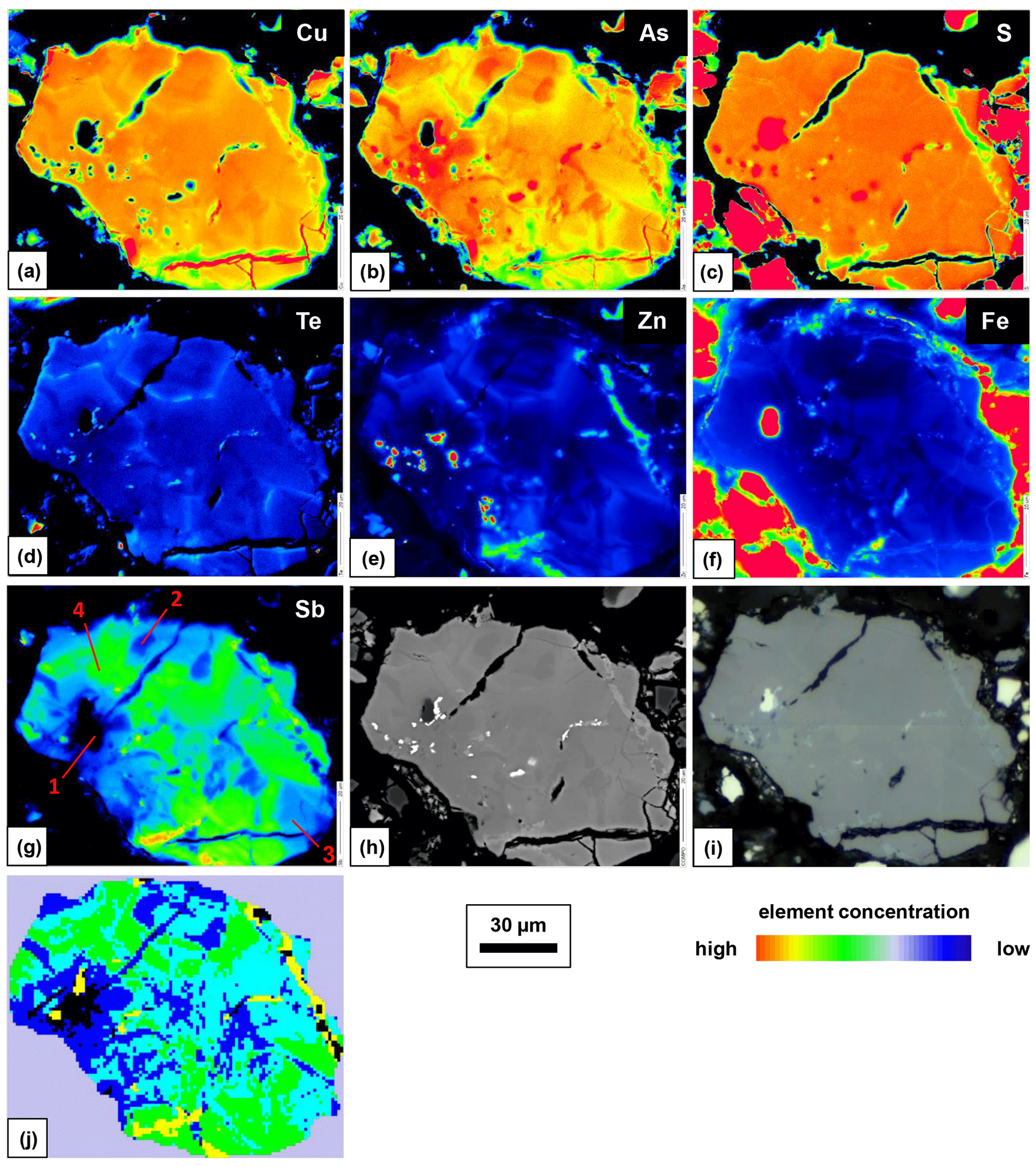
Figure 3Element distribution maps obtained with EPMA (a–g), BSE image (h), RL image (i), and phase distribution map obtained by a Raman microprobe and K-means cluster analysis (j) of fresh enargite grain.
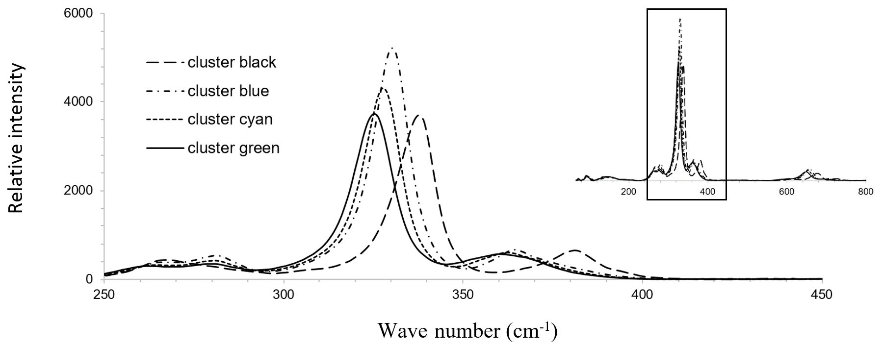
Figure 4Mean Raman spectra of the four clusters obtained by cluster analysis shown in Fig. 3j in the fresh enargite grain.
The amount of up to 1.5 at. % Sb results in the downshifting in the strongest Raman band of enargite from 337 to 325 cm−1 (Fig. 4). There is a linear dependence between the position of the strongest band and the Sb concentration (Fig. 5). The observed shifting in the other bands does not relate in a linear fashion to changes in the chemical composition. The band at 382 cm−1 also shifts to lower wavenumbers, but the shift is larger than expected. Additionally, the band at 268 cm−1 splits into two bands at 261 and 281 cm−1, suggesting multiple bands in this range whose shift and intensity variations are disproportional. However, it is important to note that the Sb-poor enargite represented by the black cluster is not pure because it contains 0.7 at. % Fe and 0.3 at. % Zn (Table 2). The FWHM of the strongest band remains unchanged, reflecting no local distortion in the structure, which confirms the simple Sb–As substitution assumed by the EPMA analyses (Fig. 2a). The intensity of the strongest band varies slightly, and the intensity of especially the clusters with moderate Sb concentration is the highest.
Table 2Chemical composition of clusters with different Sb concentrations in the fresh enargite grain shown in Fig. 3j, measured with EPMA at positions of numerals in Fig. 3g, and properties of the strongest Raman band of enargite spectra shown in Fig. 4, measured with a Raman microprobe.
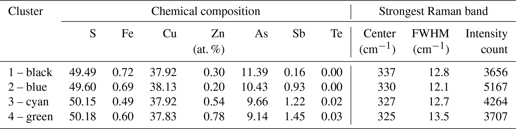
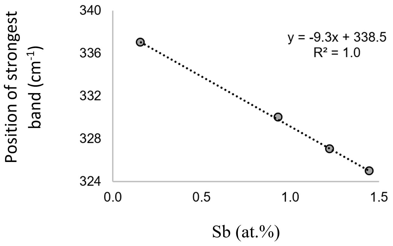
Figure 5Linear correlation between the Sb concentration and the position of the strongest Raman band of enargite in the spectra shown in Fig. 4.
Another fresh enargite grain with up to 1.2 at. % Te was investigated for its Raman spectral properties. The element distribution maps are shown in Fig. 6 in addition to the BSE and RL images. Red anomalies (false colors) in the Zn and Fe map present inclusions of sphalerite and pyrite, respectively. The enargite grain in Fig. 6 contains small amounts of Sb up to 0.5 at. % and Zn up to 0.2 at. %, whereas Te is heterogeneously distributed in the form of patchy and concentric zones. The element distribution maps reflect the element correlations determined by the random point analyses shown in Fig. 2. As previously determined, there is a negative As–Sb correlation. However, high concentrations of Te do not correlate with any of the other elements.
Raman mapping was carried out on the same Te-rich enargite grain as shown in Fig. 6. After collecting the map spectra, the Raman bands were fitted by using the WiRE software. FWHM, shift, and intensity maps were generated for the strongest band at 331–332 cm−1. Only the FWHM map is depicted in Fig. 6j because the changes in the shift and intensity of the strongest band were small. A weak correlation between the FWHM of the strongest band and Te exists (Fig. 6g and j). For comparison, single Raman spectra of sectors with low, moderate, and high Te concentrations, displayed in Fig. 6g as blue, green, and red (false colors), respectively, were extracted from the Raman map shown in Fig. 6j. The pixel positions correspond to the numerals in Fig. 6g, and the extracted spectra are displayed in Fig. 7. All three spectra are fairly similar to each other.
For a semi-quantitative comparison, the Raman bands were fitted, and the properties of the strongest band in each spectrum are listed in Table 3 together with the chemical composition of the sectors. The chemical composition of the sectors was analyzed by EPMA at the same positions. The three sectors exhibit highly variable Te concentrations ranging from 0.07 at. % to 1.24 at. %. However, the properties of the strongest Raman bands are fairly similar. There is no shift. Only the red (false colors) sector with the highest Te concentration has a slightly larger FWHM of 13.6 cm−1 compared with 11.4 and 11.5 cm−1 in the blue and green sectors with low and medium Te concentration, respectively. The intensity of the strongest band remains unchanged in all three sectors, indicating that the grain is a single crystal or at least crystals with the same orientation.
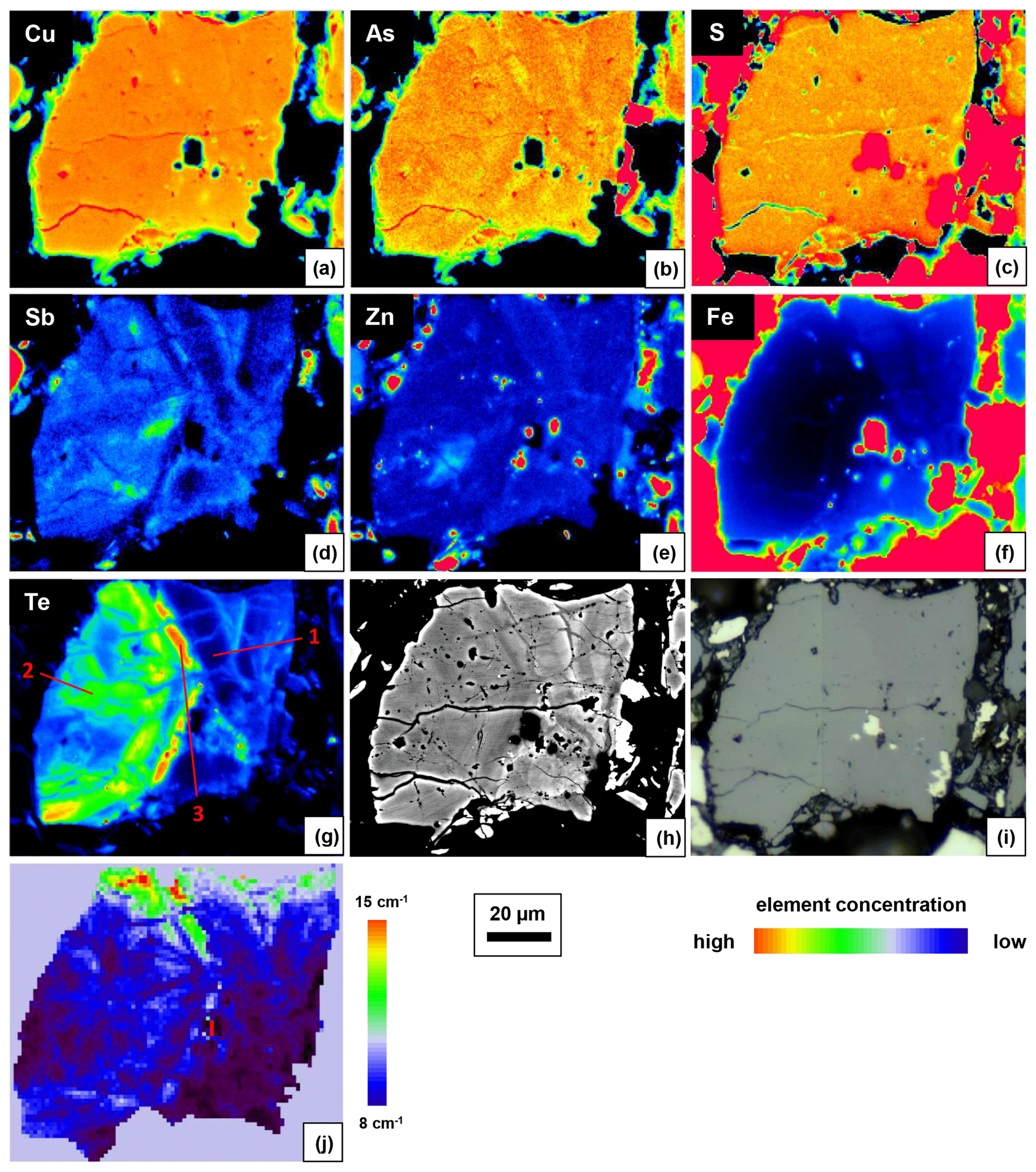
Figure 6Element distribution maps obtained with EPMA (a–g), BSE image (h), RL image (i), and FWHM of the strongest band obtained by a Raman microprobe (j) of fresh enargite grain. Note that the bright edge on the BSE image is the result of contrast maximizing and not the elevated content of heavy elements.
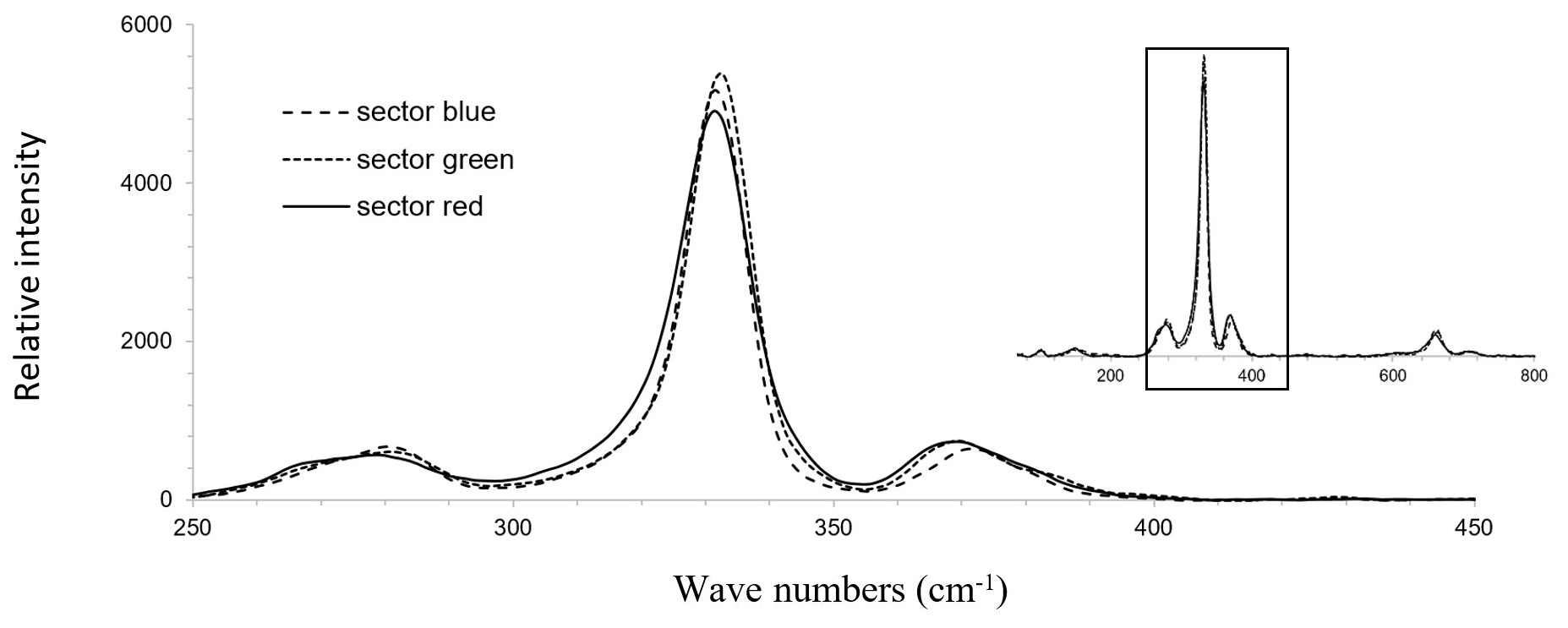
Figure 7Raman spectra of Te-rich enargite, collected from points shown in Fig. 6g in sectors with different Te concentrations in the fresh enargite grain.
Table 3Chemical composition of sectors with different Te concentrations in the fresh enargite grain, measured with EPMA at positions of numerals in Fig. 6g, and properties of the strongest Raman band of enargite spectra shown in Fig. 7, measured with a Raman microprobe.
3.2 Chemical composition of the fresh fahlore and corresponding Raman spectra
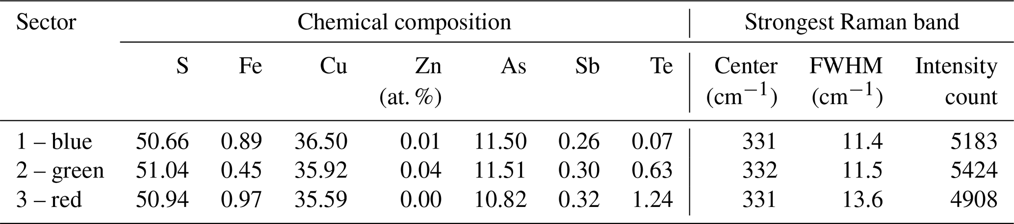
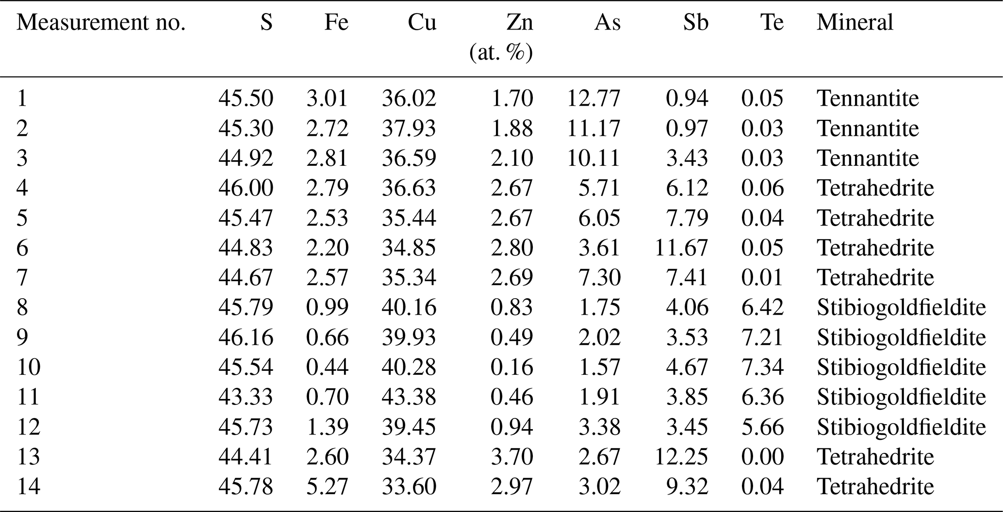
Fahlore grains in the fresh copper concentrates were randomly analyzed by EPMA (n=61). The measurement points were set in the center of the grains. The results are listed in Table S1 and are visualized in Fig. 8. We considered the As-dominant derivative to be tennantite (Cu10(Fe,Zn)2As4S13) and the Sb-dominant derivative to be tetrahedrite (Cu10(Fe, Zn)2As4S13). As suggested in Biagioni et al. (2020), the Te-dominant members are named stibiogoldfieldite (Cu12(Sb2Te2)S13) if the measured Te contents were between 1 and 3 atoms per formula unit (apfu).
A gapless negative As–Sb correlation is discernible in our data (Fig. 8a) and is well known from many previous studies on the tennantite–tetrahedrite solid solution. Tellurium correlates negatively with As and Sb as well as with Fe and Zn (Fig. 8b and c). The reason is the occupancy of Te at the (As,Sb) site via the coupled substitution Te4+ + Cu+ → (As,Sb)3+ + (Cu,Fe,Zn)2+. This substitution is valid for up to 2 Te apfu. For higher Te concentrations, the charge balance is achieved through the formation of vacancies Te4+ + (As,Sb)3+ + Cu+. This mechanism has been described in the literature (Kase, 1986; Trudu and Knittel, 1998; Moëlo et al., 2008; Makovicky and Karup-Møller, 2017). Other minor elements are Ag, Cd, and Pb, with concentrations below 0.6 at. %, 0.1 at. %, and 0.1 at. %, respectively.
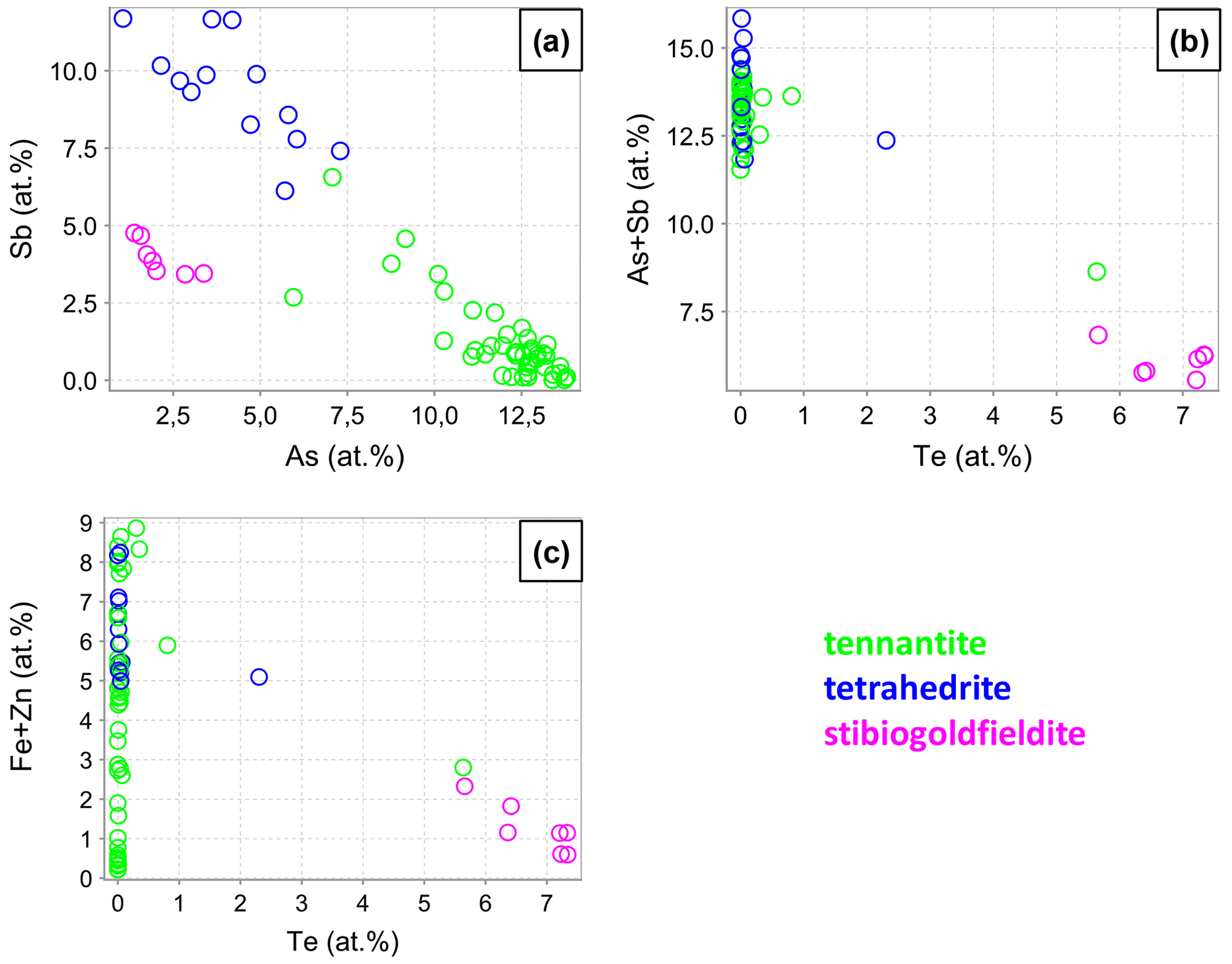
A fahlore grain was mapped by EPMA to show the different substitution mechanisms within a single grain. The selection of the grain was based on grain-scale heterogeneity, manifested by concentric zones with variable ratios. The element distribution maps are shown in Fig. 9 in addition to BSE and RL images. Additionally, EPMA point measurements were carried out along the line shown in Fig. 9i. The results are listed in Table 4. The element distribution maps reflect the element correlations obtained by the random point analyses shown in Fig. 8. The Sb–As and TeCu+–(Cu,Fe,Zn)(As,Sb)3+ substitutions were confirmed. A concentric zoning caused by variable chemical compositions can be seen (Fig. 9j). Stibiogoldfieldite containing up to 7.2 at. % Te (Table 4) presents the first generation of fahlore. Tetrahedrite containing up to 12.6 at. % Sb belongs to the second generation of fahlore. Tennantite with up to 12.9 at. % As belongs to the third generation of fahlore, deposited in interstitial volumes of the earlier minerals. The Fe concentrations in tetrahedrite and tennantite range from 2.2 at. % to 5.3 at. % and those of Zn from 1.7 at. % to 3.7 at. % (Table 4). In stibiogoldfieldite, they are lower, with a maximum of 1.3 at. % and 0.9 at. % for Fe and Zn, respectively. Further impurities are less than 0.1 at. % Ag and Cd each. The analytical totals are lower in stibiogoldfieldite compared with tennantite and tetrahedrite (Table S1), which might hint at the formation of vacancies.
Figure 9Element distribution maps obtained with EPMA (a–g), BSE image (h), RL image (i) showing the position of EPMA and Raman point analyses presented in Table 4 and Fig. 10, Te–Sb–As distribution map (j), and phase distribution map obtained by a Raman microprobe and K-means cluster analysis (k) of fresh fahlore grain.
Raman mapping was done on the same fahlore grain as shown in Fig. 9. After collecting the Raman spectra, K-means cluster analysis was performed using the WiRE software. The obtained cluster map (Fig. 9k) presents a tight correlation with the spatial distribution of the fahlore members in the grain investigated. The red, green, and blue clusters (false colors) correspond to stibiogoldfieldite, tetrahedrite, and tennantite, respectively. The cyan cluster corresponds to the As-rich tetrahedrite. Additionally, Raman point measurements were carried out along the line shown in Fig. 9i. The acquired spectra are displayed in Fig. 10.
Raman spectra of the tennantite–tetrahedrite solid solution series show characteristic bands (Figs. 10a and 11a and b) similar to those documented in Kharbish et al. (2007) and Apopei et al. (2017). The region between 200 and 400 cm−1 is the characteristic spectral region of AsS3–SbS3 vibrations (Wang et al., 1994). In this region, the most intense band of tennantite with a ratio of 0.07 occurs at 385 cm−1 and is assigned to symmetric stretching (ν1tn) of AsS3. Three weak and broad bands occur at 373, 346, and 301 cm−1 and are caused by antisymmetric stretching (ν3), symmetric bending (ν2tn), and antisymmetric bending (ν4) of AsS3, respectively. All modes shift to lower wavenumbers with an increasing ratio. The symmetric stretching mode (ν1tn) as well as symmetric bending mode (ν2tn) show the two-mode behavior, which means the modes become weaker towards the end-member tetrahedrite. Simultaneously, new bands show up at 364 cm−1 (ν1tt) and 308 cm−1 (ν2tt), attributed to the symmetric stretching and bending of SbS3, respectively. The symmetric stretching mode (ν1tt) is intense and close to the antisymmetric stretching mode (ν3) and superimposes it. Raman bands below 200 cm−1 are related to lattice vibrations (Kharbish and Jelen, 2016). In tennantite, the most intense bands are at 112, 136, and 185 cm−1 and also shift to lower wavenumbers toward tetrahedrite.
Table 4Chemical composition of tennantite, tetrahedrite, and stibiogoldfieldite in the fahlore grain at positions shown in Fig. 9i.
Stibiogoldfieldite forms a solid solution with tennantite and tetrahedrite. The vibrational modes in the tetrahedrite–tennantite solid solution series show a sequence in their wavenumbers as (Nakamoto, 1997). Thus, we assume that the strongest band at 345 cm−1 is caused by the symmetric stretching (ν1go) of TeS3 overlapping the antisymmetric stretching mode (ν3). The bands at 381 and 361 cm−1 are most probably the symmetric stretching modes (ν1tn) and (ν1tt), respectively, since the analyzed stibiogoldfieldite still contains As and Sb. The higher intensity of the ν1tt mode compared with the ν1tn mode may reflect the dominance of Sb over As. The bands at 320, 297, and 236 cm−1 can be assigned to symmetric bending modes (ν2tn), (ν2tt), and (ν2Sbgo), respectively. Whether the antisymmetric bending mode (ν4) is overlapped by ν2go or is located at a lower wavenumber is unclear due to the very broad mode at 161 cm−1. Both the symmetric stretching mode (ν1go) and symmetric bending mode (ν2go) thus exhibit a three-mode behavior. The normal modes (ν1, ν2, ν3, and ν4) as well as the lattice modes of stibiogoldfieldite occur at lower wavenumbers. The symmetric stretching mode of stibiogoldfieldite (ν1go) is much broader than that of tennantite (ν1tn) and tetrahedrite (ν1tt). The bands arising from lattice vibrational modes are also broadened.
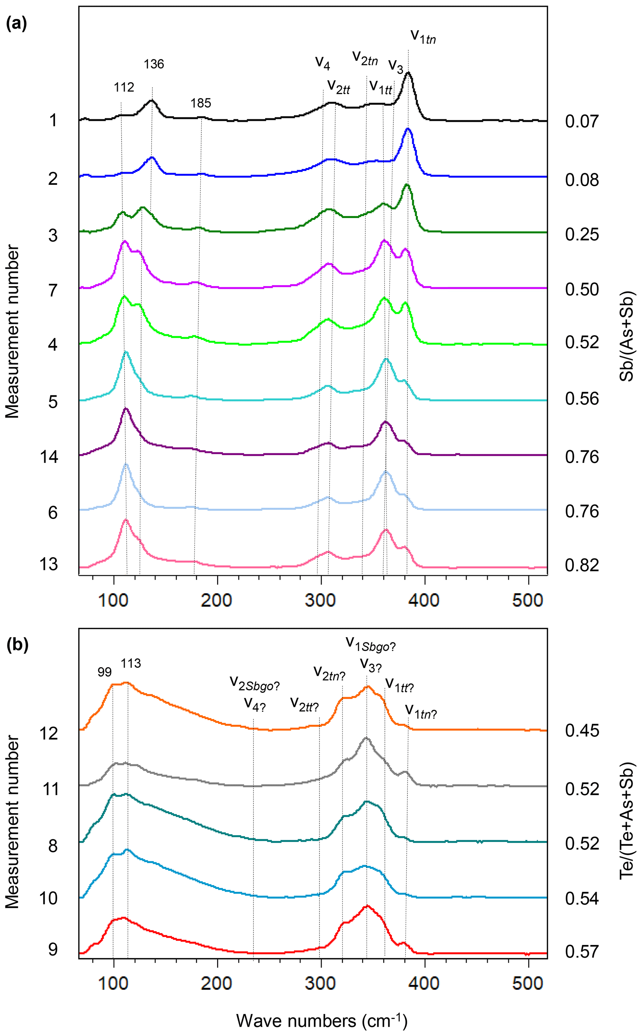
Figure 10Raman spectra of tennantite, tetrahedrite (a), and stibiogoldfieldite (b) in the fresh fahlore grain along the line shown in Fig. 9. The spectra are sorted according to the and ratios that are displayed on the right axis.
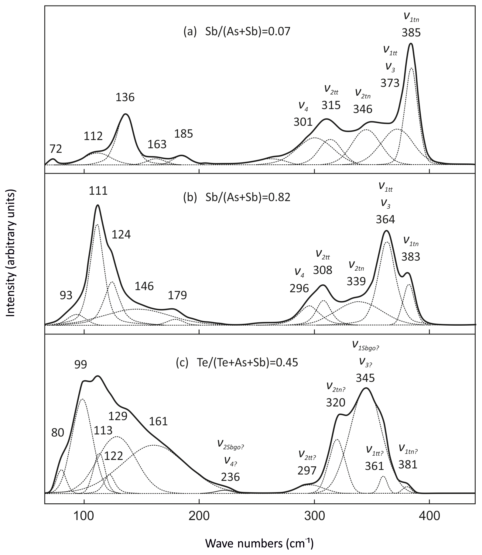
Figure 11The positions of the ν1, ν3, ν2, ν4, and lattice modes in the Raman spectra of tennantite (a), tetrahedrite (b), and stibiogoldfieldite (c).
3.3 Secondary phase in enargite
In the strongly weathered concentrates, the enargite grains contain a secondary phase whose identity was not certain. Such a phase, as mentioned in the Introduction, could be of importance for the processing and beneficiation of the ores, and was therefore characterized in terms of its chemical composition and Raman spectra.
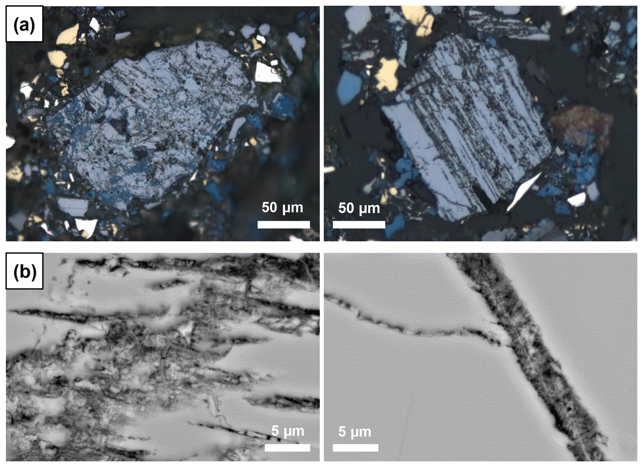
The secondary phase always occurs along cleavage planes and cracks in enargite, as seen in RL microscopy (Fig. 12a) and scanning electron microscopy (SEM) (Fig. 12b). It is frequently accompanied by covellite (Fig. 12a). Under normal illumination, it is greenish-grey and appears slightly darker than the surrounding enargite. SEM images document its fine-grained nature and porosity, which could be, at least partially, responsible for its dark appearance. It has a similar back-scattered electron (BSE) contrast to enargite, implying that the average atomic number is similar to that in enargite. The texture is fibrous or wormlike; this phase is clearly younger than the enargite host.
The secondary phase, distinct by its porosity, was analyzed by EPMA (n=44, Table S1). The main elements of the phase are Cu, As, and S, and its chemical composition is graphically compared with that of enargite and tennantite in Fig. 1. However, the chemical composition of the secondary phase is partially contaminated by the surrounding area because the analyzed area has a diameter of ca. 4 µm at the accelerating voltage of 20 kV and a beam size of 0.5 µm applied here (Batanova et al., 2015).
The elemental concentrations in the secondary phase are highly variable and range from 35 at. % to 60 at. % Cu, from 3 at. % to 14 at. % As, and from 34 at. % to 49 at. % S. Trace elements include 1.0 at. % Fe, 0.4 at. % Sb, and 0.3 at. % Zn in the median. The analytical totals of the secondary phase are also highly variable, ranging from 63 wt. % to 99 wt. %, with a median of 89.4 wt. %. The low analytical totals reflect the porous nature of the phase.
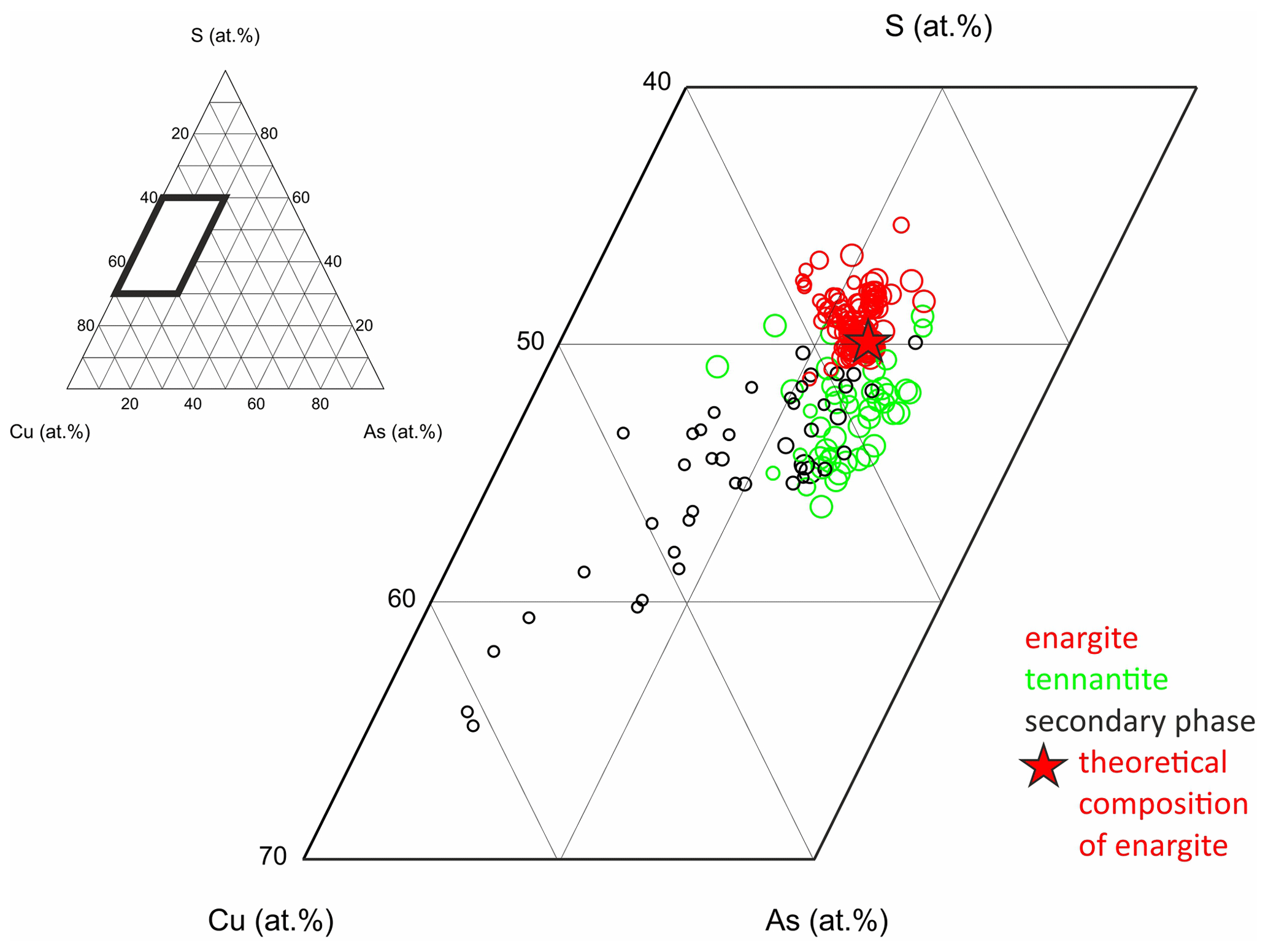
Figure 13Chemical composition of the secondary phase in weathered enargite compared to fresh enargite and tennantite; the size of the symbols is scaled by analytical totals in weight percent, and the star marks the theoretical composition of enargite.
The chemical composition of the secondary phase, enargite, and tennantite are shown in a ternary diagram of Cu, As, and S (Fig. 13). The smaller the symbols, the lower the analytical totals. The secondary phase with a chemical composition close to enargite tends to have a high analytical total. The lower the analytical total, the higher the Cu content and the lower the As and S contents. Thereby, the decrease in S is stronger than that in As, which is discussed later.
Selected grains were subjected to X-ray diffraction (XRD) analyses with a Gandolfi camera in order to obtain powder-XRD-like datasets from fresh and weathered enargite grains. The host, present in both fresh and weathered grains, was identified as an orthorhombic phase with a unit-cell volume of ∼ 300 Å3, matching the structure of enargite. Another phase present was indexed with a cubic cell and the lattice parameter a=10.223(2) Å. This lattice parameter is close to a=10.19 Å for tennantite.
The secondary phase in a weathered enargite grain was also mapped by EPMA. Grain selection was based on their larger grain size and advanced alteration (discernible in reflected polarized light) but also on the presence of primary enargite residues so that the element proportions in relatively unweathered and weathered parts of the grain can be compared. The element distribution maps are shown in Fig. 14 in addition to BSE and RL images. Enargite is replaced by the secondary phase along its cleavage planes. Only relics of enargite (Fig. 14h: pinkish gray) are left. Covellite (blue) fills the cracks of the grain and also rims the grain. The element distribution maps reflect the element proportions in the secondary phase and enargite displayed in the ternary diagram. The secondary phase is enriched in Cu and depleted in S in comparison to enargite. The As content is nearly same in both minerals. Primary enargite exhibits sector zoning with an elevated concentration of Sb. Similarly to As, the Sb content in both minerals does not differ.
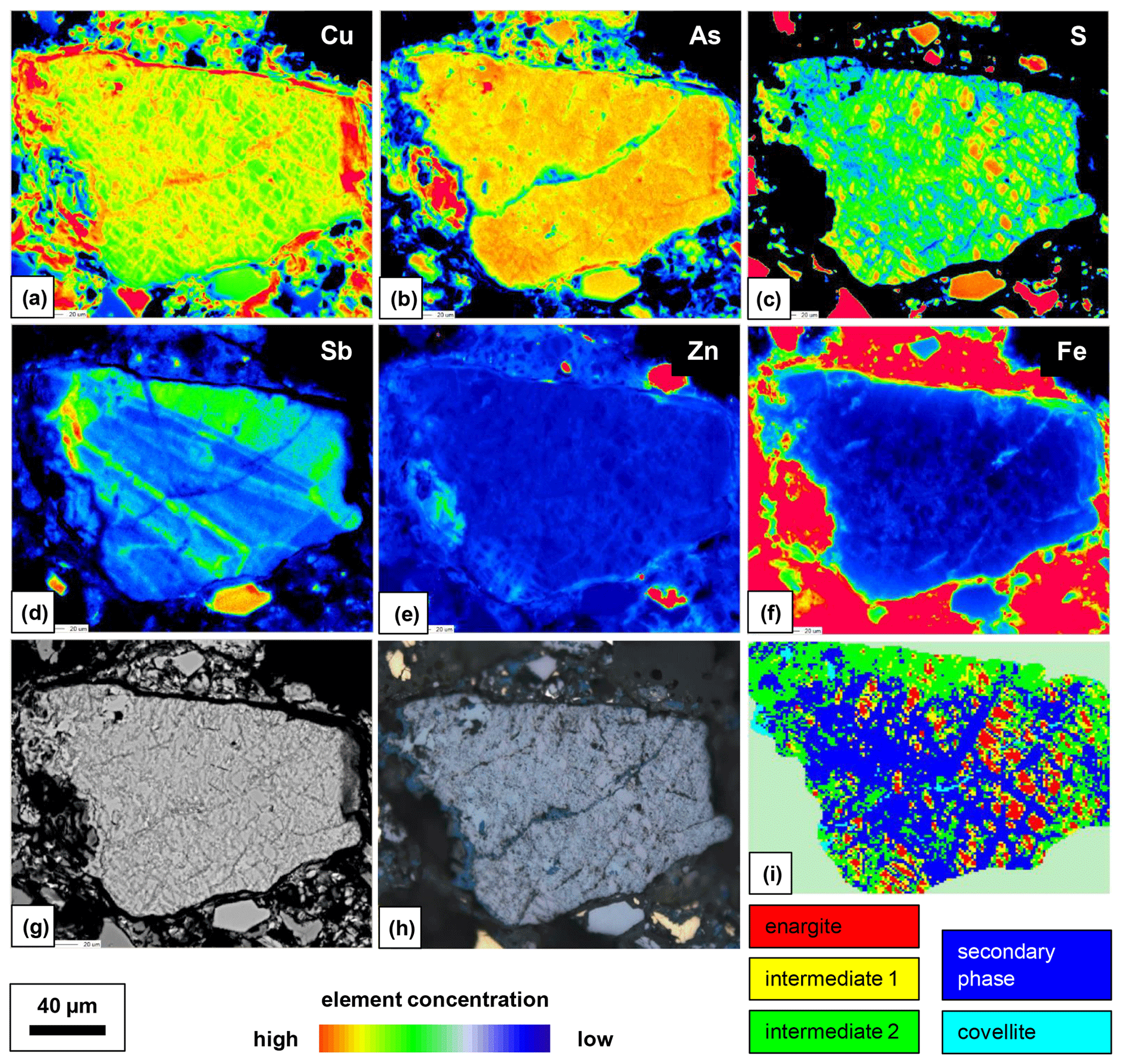
Figure 14Element distribution maps obtained with EPMA (a–f), BSE image (g), RL image (h), phase distribution map obtained by a Raman microprobe, and K-means cluster analysis (i) of a representative weathered enargite grain.
Raman mapping was carried out on the same grain as shown in Fig. 14. After collecting the Raman spectra, K-means cluster analysis was performed using the WiRE software. The obtained cluster map is shown in Fig. 14i. Two clusters, 1a and 1b, were combined into an “intermediate-phase 1” cluster and colored yellow, and two clusters, 2a and 2b, were combined into an“intermediate-phase 2” cluster and colored green for better visualization of the spatial relationships. The red cluster represents relics of enargite. The enargite relics are surrounded by the intermediate phases 1 and 2. The remaining space is filled by the blue clusters depicting the secondary phase. The altering solution has reacted with enargite along two nearly perpendicular cleavage planes of the grain. The last product formed is covellite, presented by a cyan cluster, as it rims the grain or discordantly occurs in the secondary phase.
The mean Raman spectra of the clusters are shown in Fig. 15. The primary enargite transforms successively into the intermediate product 1, then into the intermediate product 2, and finally into the secondary product. The last transformation product is covellite with the typical vibrational mode at 470 cm−1. A relic of the secondary phase is present in the covellite spectrum. The evolution of the spectra reflects the spatial relationship of the clusters shown in Fig. 14i.
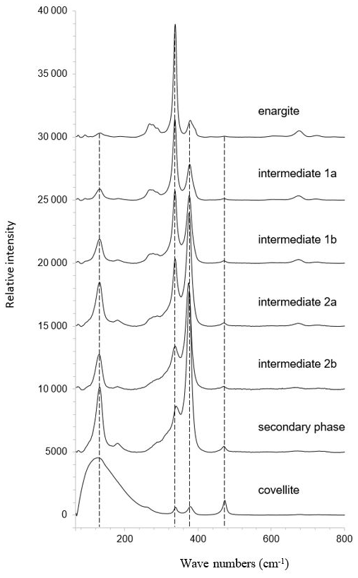
Figure 15Mean Raman spectra of the clusters shown in Fig. 14i representing enargite and enargite weathering products.
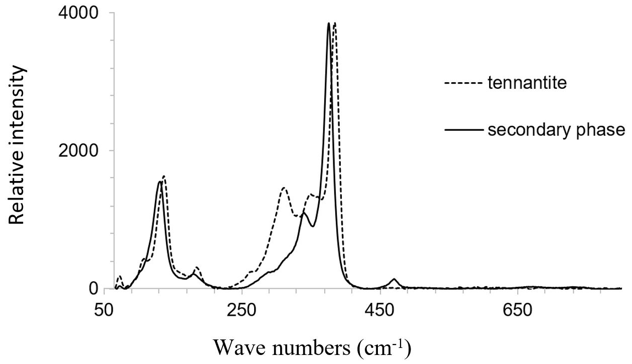
The Raman bands of the secondary phase occur in the characteristic spectral region of sulfide vibrations. Bands arising from lattice vibrations are also present. No bands were present at higher frequencies where the bands of SO4, AsO4, and H2O groups could be expected. The spectrum of the secondary phase is very similar to that of fresh tennantite. Thus, these spectra are compared in Fig. 16. The main Raman band of the secondary phase is located at a slightly lower frequency than observed for tennantite. The sharpness of the Raman bands of the secondary phase suggests that it is crystalline and not amorphous.
The secondary phase matches tennantite in terms of its chemical composition, size and shape of the unit cell, and Raman spectra. In order to increase the number of observations, a correlative Raman and X-ray structural analysis was performed on many weathered sulfide grains. Such grains were attached to a glass slide with double-sided tape and scanned with the Raman microprobe using the automatic focus-track mode. After collecting the Raman spectra, non-negative least-square component analysis was performed using the WiRE software. Raman spectra of the primary enargite, the intermediate and secondary phase (Fig. 15), and the fresh tennantite (Fig. 16) served as end-members. Brochantite and covellite were found during a manual examination of pixels that could not be assigned to an end-member and were added to the end-members, and the analysis was repeated. The obtained phase distribution map is shown in Fig. 17. The majority of the enargite grains contain the intermediate and secondary phase in addition to covellite and brochantite. Six grains seem to consist of primary tennantite because during handpicking grains it is not easy to visually distinguish enargite from tennantite. Afterwards, the grains were placed in a glass tube and measured with powder XRD. According to the qualitative XRD analysis, enargite is the main mineral. The next common phase is tennantite, followed by brochantite and quartz. No additional crystalline phase was found that would have represented the secondary phase.
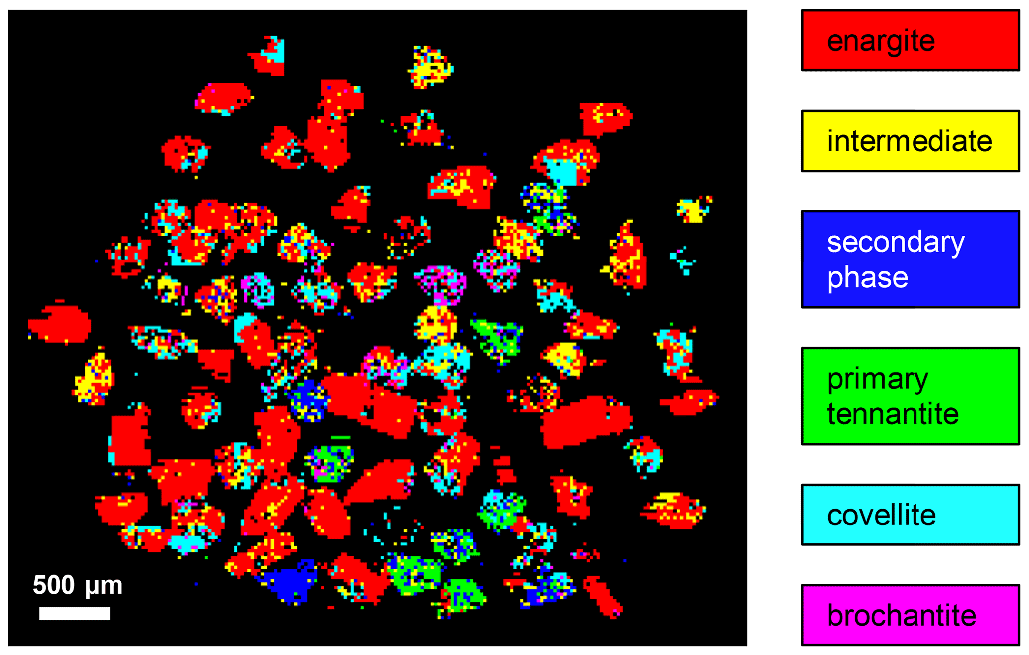
Figure 17Phase distribution map of handpicked weathered enargite grains obtained by a Raman microprobe and subsequent classification analysis.
4.1 Chemical composition of the fresh enargite and corresponding Raman spectra
A group theory treatment of the lattice vibrations in enargite predicts a total of 45 Raman active modes including 13A1, 10A2, 9B1, and 13B2 (Mernagh and Trudu, 1993). To the best of our knowledge, band assignments of enargite have not been undertaken. Strong Raman bands of enargite are observed between 250 and 400 cm−1 (Figs. 4 and 7) in a spectral region characteristic of reduced sulfur vibrations in sulfides (Wang et al., 1994). Thus, As–S vibrations are responsible for the characteristic Raman bands of enargite. The energy of the bending modes is substantially lower than that of the stretching modes, and accordingly, the bending modes are located at lower wavenumbers. In addition, the bending modes are less intense relative to the stretching modes (Tuschel, 2014). Thus, the band at 267 cm−1 may represent the bending mode, and the strongest band at 337 cm−1 may represent the stretching mode. Since arsenic in enargite is in the pentavalent state (Li et al., 1994) and in tetrahedral coordination with sulfur (Pauling and Weinbaum, 1934), one of four sulfur atoms should have a double covalent bond to arsenic (National Center for Biotechnology Information, 2022). Thus, the strongest band at 337 cm−1 is most probably the antisymmetric stretching mode. The antisymmetry of the mode is confirmed by the fact that the mode does not vanish with the Raman analyzer configured perpendicular to the incident laser polarization (Fig. S1). The mode at 382 cm−1 may represent the symmetric stretching mode similar to that in tennantite because the As–S interatomic distance is 2.25 Å in enargite as well as in tennantite (Makovicky et al., 2005; Pauling, 1970).
The current paper additionally describes the effects of Sb substitution on the Raman spectra of enargite. Antimony can substitute for As in the enargite structure with up to about 20 mol % Cu3SbS4 (Springer, 1969). The substitution mechanism was well documented by Pósfai and Buseck (1998). We have observed a gradual downshifting in the strongest band in enargite Raman spectra with an increasing Sb concentration of the mineral. The shifting is linearly proportional to the amount of Sb incorporation. In isostructural phases, the frequency of vibrational modes is shifted with the substitution of one element by another according to the “harmonic oscillator model” described by Hooke's law (Kharbish et al., 2007). Thus, increased mass and decreased bond strength by the Sb substitution cause a shift in the vibrational bands to lower frequencies. Bandwidths remain unchanged, reflecting the simple Sb–As substitution. The intensities of the strongest band slightly vary in the different clusters, which may indicate some mosaicity inside the single crystal used for our measurements.
There is a limited amount of literature on Te substitution in enargite. One of the few publications is a study on trace element substitution in enargite by Liu et al. (2019). The authors proposed a coupled substitution mechanism of Te4+ with Fe2+ or Zn2+ for Cu+ and As5+. Our data support this substitution mechanism, as Te, Fe, and Zn concentrations negatively correlate with As, Sb, and Cu. The coupled substitution mechanism would lead to a broadening of the Raman bands, but our data show that the FWHM of the strongest band does not increase with Te incorporation. Most importantly, unlike Sb, uptake of Te does not lead to a band shift, even though it is heavier than Sb. Deyell-Wurst and Hedenquist (2011) suggested that Au in enargite is either structurally bound within the crystal structure or it occurs as submicron native Au inclusions. Similarly, Te could occur in the form of submicron native Te inclusions.
4.2 Chemical composition of the fresh fahlore and corresponding Raman spectra
Raman spectra of the solid solution series between tennantite and tetrahedrite change with the ratio, as already seen by Kharbish et al. (2007) and Apopei et al. (2017). All Raman bands shift to a lower frequency with increasing Sb concentration. Two-mode behavior was observed for the bands ν1 and ν2. Kharbish et al. (2007) assumed that this is the result of a possible short-range order, i.e., clustering of SbS3 and AsS3 groups. Two stretching vibrations, ν1 and ν3, and two bending vibrations, ν2 and ν4, are close in energy and overlap (Nakamoto, 1997). Almost all modes could be deconvoluted by curve fitting; only the overlap of ν1tt and ν3 modes remains unresolved.
To our knowledge, the Raman spectrum of stibiogoldfieldite has not been reported yet. All modes, including lattice modes, occur at frequencies lower than what are typical for tetrahedrite due to the substitution of the heavier element Te for As and Sb. Three-mode behavior was observed for the bands ν1 and ν2. Although stibiogoldfieldite forms a continuous solid solution with tennantite and tetrahedrite, the strongest mode of stibiogoldfieldite (ν1Sbgo) is strongly broadened, indicating a development of second-order bands arising from the modifications in the crystal structure. The most likely reason is the coupled substitution of Te4+ with Cu+ for As3+ and Sb3+ with Fe2+ and Zn2+. Additionally, the lattice vibrational modes are broadened because they involve a significant contribution of atomic motion from the substituted atom (Tuschel, 2017).
4.3 Secondary phase in enargite
Enargite, as most sulfides, is unstable in oxidizing and acidic environments and is likely to dissolve. The acidity at the studied site is generated by oxidative dissolution of pyrite, the most common mineral in the analyzed concentrate. Oxidative dissolution of enargite is in itself an acid-generating process as well (Plumlee, 1999). The dissolution rate of enargite is higher in the presence of a strong oxidizing agent such as Fe3+ (Davis et al., 1992; Dutrizac and MacDonald, 1972; Elkina et al., 2020). Therefore, the dissolution of enargite may be facilitated by the Fe3+ that is released by the oxidation of pyrite or chalcopyrite in the concentrate. All these processes are accelerated by comminution of the ores (Welham, 2001).
In this study, we observed replacement of enargite by a secondary phase with high porosity and a fibrous or wormlike texture. Gandolfi camera measurements showed that the secondary phase is cubic, with unit-cell parameters matching those of tennantite. All Raman bands of the secondary phase appear in the characteristic spectral region of sulfide vibrations (Wang et al., 1994) and are similar to those of tennantite. No bands were present at a higher frequency, where sulfate, arsenate, and OH bands occur. The strongest band at 337 cm−1, assumed to be the antisymmetric stretching of As–S, weakens, indicating breaking of the As–S bonds. In particular, the sulfur that is bonded to arsenic and has no bonding to Cu may be preferentially released. This supposition can be supported by the fact that the secondary phase is more depleted in S than in As and is enriched in Cu. The released S2− may oxidize to polysulfide moieties or elemental sulfur S0, which can be detected from a weak band at 470 cm−1. A formation of polysulfide or elemental sulfur on the oxidized surface of enargite has indeed been observed frequently (Rossi et al., 2001; Viñals et al., 2003; Dutrizac and MacDonald, 1972; Ásbjörnsson et al., 2004; Elsener et al., 2007; Sasaki et al., 2010; Plackowski, 2014). Sulfur oxidation can be coupled to arsenic reduction of As5+ to As3+. The formation of As3+ upon weathering of enargite is feasible, since arsenolite or claudetite (both As(III) oxides) occur in some enargite-bearing deposits (Lattanzi et al., 2008). Simultaneously, the weak band at 381 cm−1 enhances during the transformation of enargite to the secondary phase, which may represent the symmetric stretching of As–S, as in tennantite.
Other studies have detected the formation of Cu(II)–O bonds, sulfate (Rossi et al., 2001), and As(V)–O bonds (Viñals et al., 2003) on the surface of untreated natural enargite samples. During oxidative dissolution of enargite in acidic solutions with ferric iron, a polysulfide film and a Cu-deficient layer were formed (Elsener et al., 2007). In the field, such as open pits and waste dumps, enargite is often replaced by scorodite and cuprian melanterite (Lattanzi et al., 2008). We did not observe such minerals, but we found the tennantite-like phase and covellite. Our findings agree with early microscopic work of Schneiderhöhn (1922). He observed that enargite often undergoes transformation into an isotropic phase with a greenish tint without a noticeable chemical change. In this work, we demonstrated that this “greenish enargite” is Cu–As fahlore, which chemically differs little from ordinary tennantite. Hence, this tennantite is a complex secondary sulfide. Similar processes, leading to complex secondary sulfides, have recently been reported by Haase et al. (2022). Here, the formation of such secondary sulfides was observed on the nanometer scale in TEM and was rationalized in terms of different diffusion rates of cations from the structure of the primary sulfide.
Additionally, tennantite oxidizes more slowly than enargite (Fullston et al., 1999) and can thus persist for a longer time in an oxidative weathering environment. According to the Eh–pH diagram for the aqueous Cu–As–S system calculated by Gow et al. (2014), enargite can transform into tennantite at a low pH (pH < 2) and at slightly oxidizing conditions (Eh > 0), but the stability field of tennantite is rather narrow. Furthermore, a decomposition of enargite through the formation of tennantite as an intermediate compound was observed in an oxidizing atmosphere; this tennantite was subsequently transformed into solid chalcocite. This process, however, occurred at roasting temperatures between 375 and 450 ∘C (Padilla et al., 2012).
This study revealed that Raman spectra carry information that can be used to decipher the ratio in enargite and fahlore. With an increasing Sb concentration, the strongest Raman band of enargite gradually shifts to lower frequencies. Similarly, the continuous solid solution series from tetrahedrite to tennantite are manifested in gradual changes in their Raman spectra. Raman spectra of stibiogoldfieldite are presented for the first time. All modes, including lattice modes, are strongly broadened and shifted to lower frequencies compared with those of tetrahedrite and tennantite, owing to the substitution of the heavier Te for Sb or As. The observed spectral shifts can find their use in industrial processes in order to optimize ore beneficiation and to minimize the environmental impact.
Enargite in the concentrate initially weathers to a fine-grained, fibrous, or wormlike phase. This phase was identified as secondary tennantite, a transient sulfide mineral that is able to retain arsenic temporarily. Experimental evidence, amassed in earlier literature, shows that the arsenic is eventually lost, either completely into the environment or partially, being retained by scorodite or similar minerals.
All raw data can be provided by the corresponding authors upon request.
The supplement related to this article is available online at: https://doi.org/10.5194/ejm-35-737-2023-supplement.
KB: conceptualization, methodology, investigation, writing (original draft), visualization. JM: writing (review and editing). JAM: writing (review and editing), funding acquisition. JP: investigation, writing (review and editing). DR: writing (review and editing).
The contact author has declared that none of the authors has any competing interests.
Publisher’s note: Copernicus Publications remains neutral with regard to jurisdictional claims in published maps and institutional affiliations.
We thank Simon Goldmann and Christian Wöhrl for their support with EPMA, Kristian Ufer for powder X-ray diffraction analysis, Dominic Göricke for technical support, and Donald Henry and Andreas Heiner for sample preparation at the Federal Institute for Geosciences and Natural Resources. We also thank the anonymous reviewers and the editor for their insightful comments and suggestions.
The research is funded by the Federal Ministry of Education and Research (BMBF) within the Client II ReAK project (grant no. 033R205D).
This paper was edited by Qun-Ke Xia and reviewed by two anonymous referees.
Apopei, A., Damian, G., Buzgar, N., Buzatu, A., Andráš, P., and Milovská, S.: The determination of the content in natural tetrahedrite-tennantite and bournonite-seligmannite solid solution series by means of Raman spectrometry, Mineral. Mag., 81, 1439–1456, https://doi.org/10.1180/minmag.2017.081.008, 2017.
Ásbjörnsson, J., Kelsall, G. H., Pattrick, R. A. D., Vaughan, D. J., Wincott, P. L., and Hope, G. A.: Electrochemical and Surface Analytical Studies of Enargite in Acid Solution, J. Electrochem. Soc., 151, E250, https://doi.org/10.1149/1.1756892, 2004.
Batanova, V. G., Sobolev, A. V., and Kuzmin, D. V.: Trace element analysis of olivine: High precision analytical method for JEOL JXA-8230 electron probe microanalyser, Chem. Geol., 419, 149–157, https://doi.org/10.1016/j.chemgeo.2015.10.042, 2015.
Biagioni, C., George, L., Cook, N., Makovicky, E., Moëlo, Y., Pasero, M., Sejkora, J., Stanley, C., Welch, M., and Bosi, F.: The tetrahedrite group: Nomenclature and classification, Am. Mineral., 105, 109–122, https://doi.org/10.2138/am-2020-7128, 2020.
Chen, Y., Zhu, S., Taskinen, P., Peng, N., Peng, B., Jokilaakso, A., Liu, H., Liang, Y., Zhao, Z., and Wang, Z.: Treatment of high-arsenic copper smelting flue dust with high copper sulfate: Arsenic separation by low temperature roasting, Miner. Eng., 164, 106796, https://doi.org/10.1016/j.mineng.2021.106796, 2021.
Da Pelo, S.: Environmental geochemistry and mineralogy of active and abandoned mine sites, PhD Thesis in Earth Sciences, Cagliari-Genova-Torino, 1998 (in Italian, extended abstract in English in Plinius 21, 70–74, 1999).
Davis, A., Ruby, M. V., and Bergstrom, P. D.: Bioavailability of arsenic and lead in soils from the Butte, Montana, mining district, Environ. Sci. Technol., 26, 461–468, https://doi.org/10.1021/es00027a002, 1992.
Deyell-Wurst, C. and Hedenquist, J.: Trace element geochemistry of enargite in the Mankayan district, PHILIPPINES, Econ. Geol., 106, 1465–1478, https://doi.org/10.2113/econgeo.106.8.1465, 2011.
Dold, B.: Sustainability in metal mining: from exploration, over processing to mine waste management, Rev. Environ. Sci. Bio, 7, 275–285, https://doi.org/10.1007/s11157-008-9142-y, 2008.
Dutrizac, J. E. and MacDonald, R. J. C.: The kinetics of dissolution of enargite in acidified ferric sulphate solutions, Can. Metall. Quart., 11, 469–476, https://doi.org/10.1179/cmq.1972.11.3.469, 1972.
Elkina, Y. A., Melnikova, E. A., Melamud, V. S., and Bulaev, A. G.: Bioleaching of Enargite and Tennantite by Moderately Thermophilic Acidophilic Microorganisms, Microbiology, 89, 413–424, https://doi.org/10.1134/S0026261720040050, 2020.
Elsener, B., Atzei, D., Fantauzzi, M., and Rossi, A.: Electrochemical and XPS surface analytical studies on the reactivity of enargite, Eur. J. Mineral., 19, 353–361, https://doi.org/10.1127/0935-1221/2007/0019-1729, 2007.
Fullston, D., Fornasiero, D., and Ralston, J.: Zeta potential study of the oxidation of copper sulfide minerals, Colloids Surface. A, 146, 113–121, 1999.
Gow, R., Huang, H., and Young, C.: Utility of mass-balanced EH-pH diagrams I – Applications of Gibbs' Phase Rule, 2014 SME Annual Meeting and Exhibit, SME 2014: Leadership in Uncertain Times, Miner. Metall. Proc., 33, 794–800, https://doi.org/10.19150/mmp.6622, 2014.
Haase, P., Kiefer, S., Pollok, K., Drahota, P., and Majzlan, J.: Weathering of stannite–kësterite [Cu2(Fe,Zn)SnS4] and the environmental mobility of the released elements, Eur. J. Mineral., 34, 493–506, https://doi.org/10.5194/ejm-34-493-2022, 2022.
Herreros, O., Quiroz, R., Hernández, M. C., and Viñals, J.: Dissolution kinetics of enargite in dilute Cl2/Cl− media, Hydrometallurgy, 64, 153–160, https://doi.org/10.1016/S0304-386X(02)00034-8, 2002.
Ishihara, S., Shinoda, K., and Kano, J.: Mechanochemical Treatment to Remove Arsenic from Copper Ore, Minerals, 9, 349, https://doi.org/10.3390/min9060349, 2019.
Karanovi, L. J., Cvetkovi, L. J., Poleti, D., Bali-uni, T., and Makovicky, E.: Crystal and absolute structure of enargite from Bor (Serbia), Neues Jb. Miner. Monat., 2002, 241–253, https://doi.org/10.1127/0028-3649/2002/2002-0241, 2002.
Kase, K.: Tellurian tennantite from the besshi-type deposits in the Sambagawa metamorphic belt, Japan, Can. Mineral., 24, 399–404, 1986.
Kharbish, S. and Jelen, S.: Raman spectroscopy of the Pb-Sb sulfosalts minerals: Boulangerite, jamesonite, robinsonite and zinkenite, Vib. Spectrosc., 85, 157–166, https://doi.org/10.1016/j.vibspec.2016.04.016, 2016.
Kharbish, S., Libowitzky, E., and Beran, A.: The effect of As-Sb substitution in the Raman spectra of tetrahedrite-tennantite and pyrargyrite-proustite solid solutions, Eur. J. Mineral., 19, 567–574, https://doi.org/10.1127/0935-1221/2007/0019-1737, 2007.
Lattanzi, P., Da Pelo, S., Musu, E., Atzei, D., Elsener, B., Fantauzzi, M., and Rossi, A.: Enargite oxidation: A review, Earth-Sci. Rev., 86, 62–88, https://doi.org/10.1016/j.earscirev.2007.07.006, 2008.
Li, D., Bancroft, G. M., Kasrai, M., Fleet, M. E., Feng, X. H., Yang, B. X., and Tan, K. H.: S K- and L-edge XANES and electronic structure of some copper sulfide minerals, Phys. Chem. Miner., 21, 317–324, https://doi.org/10.1007/BF00202096, 1994.
Li, T., Zhang, Y., Zhang, B., Jiao, F., and Qin, W.: Flotation separation of enargite from complex copper concentrates by selective surface oxidation, Physicochem. Probl. Mi., 55, 852–864, https://doi.org/10.5277/ppmp19005, 2019.
Liu, W., Cook, N. J., Ciobanu, C. L., and Gilbert, S. E.: Trace element substitution and grain-scale compositional heterogeneity in enargite, Ore Geol. Rev., 111, 103004, https://doi.org/10.1016/j.oregeorev.2019.103004, 2019.
Long, G., Peng, Y., and Bradshaw, D.: A review of copper–arsenic mineral removal from copper concentrates, Miner. Eng., 36–38, 179–186, https://doi.org/10.1016/j.mineng.2012.03.032, 2012.
Long, G., Peng, Y., and Bradshaw, D.: Flotation separation of copper sulphides from arsenic minerals at Rosebery copper concentrator, Miner. Eng., 66–68, 207–214, https://doi.org/10.1016/j.mineng.2014.04.003, 2014.
Makovicky, E. and Karup-Møller, S.: Exploratory Studies of Substitutions in the Tetrahedrite/tennantite–goldfieldite Solid Solution, Can. Mineral., 55, 233–244, https://doi.org/10.3749/canmin.1600067, 2017.
Makovicky, E., Karanovic, L., Poleti, D., Balic-Zunic, T., and Paar, W.: Crystal structure of copper-rich unsubstituted tennantite, Cu12.5As4S13, Can. Mineral., 43, 679–688, https://doi.org/10.2113/gscanmin.43.2.679, 2005.
Mernagh, T. P. and Trudu, A. G.: A laser Raman microprobe study of some geologically important sulphide minerals, Chem. Geol., 103, 113–127, https://doi.org/10.1016/0009-2541(93)90295-T, 1993.
Moëlo, Y., Makovicky, E., Secretary, A., Mozgova, N., Jambor, J., Cook, N., Pring, A., Paar, W., Nickel, E., Graeser, S., Sven, K.-M., Balic-Zunic, T., Mumme, W., Vurro, F., Topa, D., Bindi, L., Bente, K., and Shimizu, M.: Sulfosalt systematics: A review. Report of the sulfosalt sub-committee of the IMA Commission on Ore Mineralogy, Eur. J. Mineral, 20, 7–46, https://doi.org/10.1127/0935-1221/2008/0020-1778, 2008.
Nakamoto, K.: Infrared and Raman spectra of inorganic and coordination compounds. Part A: Theory and applications in inorganic chemistry, John Wiley & Sons, Inc., New York, 408 pp., ISBN 978-0471163947, 1997.
National Center for Biotechnology Information: PubChem Compound Summary for CID 177517, Enargite (Cu3(AsS4), https://pubchem.ncbi.nlm.nih.gov/compound/Enargite-_Cu3_AsS4 (last access: 10 October 2022), 2022.
O'Day, P.: Chemistry and Mineralogy of Arsenic, Elements, 2, 77–83, https://doi.org/10.2113/gselements.2.2.77, 2006.
Padilla, R., Girón, D., and Ruiz, M. C.: Leaching of enargite in H2SO4–NaCl–O2 media, Hydrometallurgy, 80, 272–279, https://doi.org/10.1016/j.hydromet.2005.08.006, 2005.
Padilla, R., Aracena, A., and Ruiz, M. C.: Reaction Mechanism and Kinetics of Enargite Oxidation at Roasting Temperatures, Metall. Mater. Trans. B, 43, 1119–1126, https://doi.org/10.1007/s11663-012-9675-x, 2012.
Pauling, L.: Crystallography and chemical bonding of sulfide minerals, Min. Soc. Am. Spec. Pap, 3, 125–131, 1970.
Pauling, L. and Weinbaum, S.: The Crystal Structure of Enargite, Cu3AsS4, Z. Kristallogr., 88, 48–53, https://doi.org/10.1524/zkri.1934.88.1.48, 1934.
Pfitzner, A. and Bernert, T.: The system Cu3AsS4–Cu3SbS4 and investigations on normal tetrahedral structures, Z. Kristallogr., 219, 20–26, https://doi.org/10.1524/zkri.219.1.20.25398, 2004.
Pfitzner, A., Evain, M., and Petrícek, V.: Cu12Sb4S13: A Temperature-Dependent Structure Investigation, Acta Crystallogr. B, 53, 337–345, https://doi.org/10.1107/S0108768196014024, 1997.
Plackowski, C.: Investigation of the surface species formed on enargite in electrochemically controlled oxidising environments and in the presence of flotation collectors, PhD Thesis, School of Chemical Engineering, The University of Queensland, https://doi.org/10.14264/uql.2014.476, 2014.
Plumlee, G.: The environmental geology of mineral deposits, Rev. Econ. Geol., 6A, 71–116, 1999.
Pósfai, M. and Buseck, P.: Relationships between microstructure and composition in enargite and luzonite, Am. Mineral., 83, 373–382, https://doi.org/10.2138/am-1998-3-422, 1998.
Rigaku Oxford Diffraction: CrysAlisPro Software system, version 1.171.39.46, Rigaku Corporation, Oxford, UK, 2019.
Rossi, A., Atzei, D., Da Pelo, S., Frau, F., Lattanzi, P., England, K. E. R., and Vaughan, D. J.: Quantitative X-ray photoelectron spectroscopy study of enargite (Cu3AsS4) surface, Surf. Interface Anal., 31, 465–470, https://doi.org/10.1002/sia.1072, 2001.
Rumball, J. A. and Richmond, G. D.: Measurement of oxidation in a base metal flotation circuit by selective leaching with EDTA, Int. J. Miner. Process., 48, 1–20, https://doi.org/10.1016/S0301-7516(96)00010-5, 1996.
Sasaki, K., Takatsugi, K., Ishikura, K., and Hirajima, T.: Spectroscopic study on oxidative dissolution of chalcopyrite, enargite and tennantite at different pH values, Hydrometallurgy, 100, 144–151, https://doi.org/10.1016/j.hydromet.2009.11.007, 2010.
Schneiderhöhn, H.: Anleitung zur mikroskopischen bestimmung und untersuchung von erzen und aufbereitungsprodukten besonders im auffallenden licht, Gesellschaft Deutscher Metallhütten- und Bergleute, ISBN 978-0364640548, 1922.
Senior, G. and Trahar, W. J.: The influence of metal hydroxides and collector on the flotation of chalcopyrite, Int. J. Miner. Process., 33, 321–341, 1991.
Sillitoe, R. H.: Porphyry Copper Systems*, Econ. Geol., 105, 3–41, https://doi.org/10.2113/gsecongeo.105.1.3, 2010.
Springer, G.: Compositional variations in enargite and luzonite, Miner. Deposita, 4, 72–74, 1969.
Takéuchi, Y. and Sadanaga, R.: Structural principles and classification of sulfosalts, Z. Kristallogr., 130, 346–368, 1969.
Tayebi-Khorami, M., Manlapig, E., Forbes, E., Bradshaw, D., and Edraki, M.: Selective flotation of enargite from copper sulphides in Tampakan deposit, Mineral. Eng., 112, 1–10, https://doi.org/10.1016/j.mineng.2017.06.021, 2017.
Tayebi-Khorami, M., Manlapig, E., Forbes, E., Edraki, M., and Bradshaw, D.: Effect of surface oxidation on the flotation response of enargite in a complex ore system, Mineral. Eng., 119, 149–155, https://doi.org/10.1016/j.mineng.2018.01.024, 2018.
Trudu, A. G. and Knittel, U.: Crystallography, mineral chemistry and chemical nomenclature of goldfieldite, the tellurian member of the tetrahedrite solid-solution series, Can. Mineral., 36, 1115–1137, 1998.
Tuschel, D.: Practical Group Theory and Raman Spectroscopy, Part II: Application of Polarization, Spectroscopy, 29, 14–22, 2014.
Tuschel, D.: Effect of dopants or impurities on the raman spectrum of the host crystal, Spectroscopy (Santa Monica), 32, 13–18, 24, 2017.
Viñals, J., Roca, A., Hernández, M. C., and Benavente, O.: Topochemical transformation of enargite into copper oxide by hypochlorite leaching, Hydrometallurgy, 68, 183–193, https://doi.org/10.1016/S0304-386X(02)00200-1, 2003.
Wang, A., Han, J., Guo, L., Yu, J., and Zeng, P.: Database of Standard Raman Spectra of Minerals and Related Inorganic Crystals, Appl. Spectrosc., 48, 959–968, 1994.
Welham, N. J.: Mechanochemical processing of enargite (Cu3AsS4), Hydrometallurgy, 62, 165–173, 2001.
Wilkomirsky, I., Parra, R., Parada, F., Balladares, E., Etcheverry, J., and Díaz, R.: Partial Roasting of High-Arsenic Copper Concentrates, Metall. Mater. Trans. B, 51, 2030–2038, 10.1007/s11663-020-01893-x, 2020.