the Creative Commons Attribution 4.0 License.
the Creative Commons Attribution 4.0 License.
 | 30 Jul 2021
The intracrystalline microstructure of Monte Fico lizardite, by optics, μ-Raman spectroscopy and TEM
Giancarlo Capitani
Roberto Compagnoni
Serena Botta
Marcello Mellini
The Monte Fico lizardite crystals have an internal skeletal spongy microstructure, formed by two micrometric domains having different optical reliefs. This intracrystalline microstructure parallels the previously reported intercrystalline arrangement, consisting of lizardite prisms within a chrysotile plus polygonal serpentine matrix. In the high-wavenumber region, the larger and more abundant domains (that represent approximately 87 % of the total field view) produce μ-Raman spectra characterized by two major peaks at 3686 and 3705 cm−1. The smaller, less abundant domains present a wide band confined between these wavenumbers. These features are interpreted as lizardite and chrysotile, respectively. Raman results are confirmed by TEM, which emphasizes the presence of well-recognizable polygonal serpentine too. Tight crystallographic control exists between lizardite and this first serpentine generation. A second serpentine generation occurs perpendicularly to the first one. The lizardite crystals grew up with a skeletal habit, whereas chrysotile fibres and polygonal serpentine filled the voids, growing epitactically on the lizardite crystals, with fast crystal growth in a fluid-rich environment.
- Article
(14162 KB) - Full-text XML
- BibTeX
- EndNote


During a μ-Raman study of serpentine minerals (Compagnoni et al., 2021), the careful microscopic examination of prismatic lizardite-1T crystals from the Monte Fico quarry, the island of Elba, showed “spongy” intracrystalline microstructure, especially evident in sections perpendicular to the c axis. This observation aroused renewed interest over a mineral occurrence largely studied after its first report (Mellini and Viti, 1994).
Actually, the discovery of abundant euhedral crystals, up to mm in size, had allowed several subsequent studies, overcoming the limits constituted by the usual tiny size and poor crystallinity of lizardite.
At Monte Fico, euhedral lizardite-1T crystals occur embedded within an interstitial matrix consisting of variable amounts of chrysotile and minor polygonal serpentine. Viti and Mellini (1997) estimated the chemical compositions
for lizardite and chrysotile, respectively. Based upon Mössbauer and Fourier transform IR data, Fuchs et al. (1998) proposed for lizardite the improved formula
The Monte Fico lizardite has been extensively studied from many points of view. Among these, Gregorkiewitz et al. (1996) performed neutron Rietveld refinement at different temperatures. Monte Fico lizardite was used by Rinaudo et al. (2003) as Raman reference material and by Auzende et al. (2004) during high-pressure (HP) Raman investigation. Hilairet et al. (2006) determined the serpentine P–V equation of state. Hirose et al. (2006) studied its mechanical behaviour and microstructural evolution during dehydration reaction, and subsequently Viti and Hirose (2009) performed high-temperature torsion experiments. It has been used in thermogravimetric study by Viti (2010) and in high-temperature Raman and FTIR study of phase transformations by Trittschack et al. (2012). Amiguet et al. (2012) studied its rheological behaviour. Lacinska et al. (2016) used it for study of carbon capture by mineralization. Gailhanou et al. (2018) determined its thermodynamic properties by calorimetry.
Therefore, after so much work, it was amazing to find now, just by optical microscopy, unexpected microstructural features, possibly capable of exposing bias in previous characterizations.
Fresh serpentinites are exposed in two large disused quarries located in Monte Fico (Viti and Mellini, 1997). The serpentinites, fractured by tectonics, consist of subrounded blocks several metres thick, separated by joints filled with polygonal serpentine or macrocrystalline lizardite veins. The blocks, usually massive, preserve well the original peridotite structure, but the original high-temperature minerals were pseudomorphically replaced during low-temperature serpentinization, which mostly occurred on the ocean floor (e.g. Viti and Mellini, 1998). In addition to the previous joint-filling veins, several other kinds of vein occur: chrysotile veins; antigorite veins (Viti and Mellini, 1996); lizardite–chrysotile veins; and more complex veins, where chrysotile, polygonal serpentine and lizardite are present in variable relative amounts.
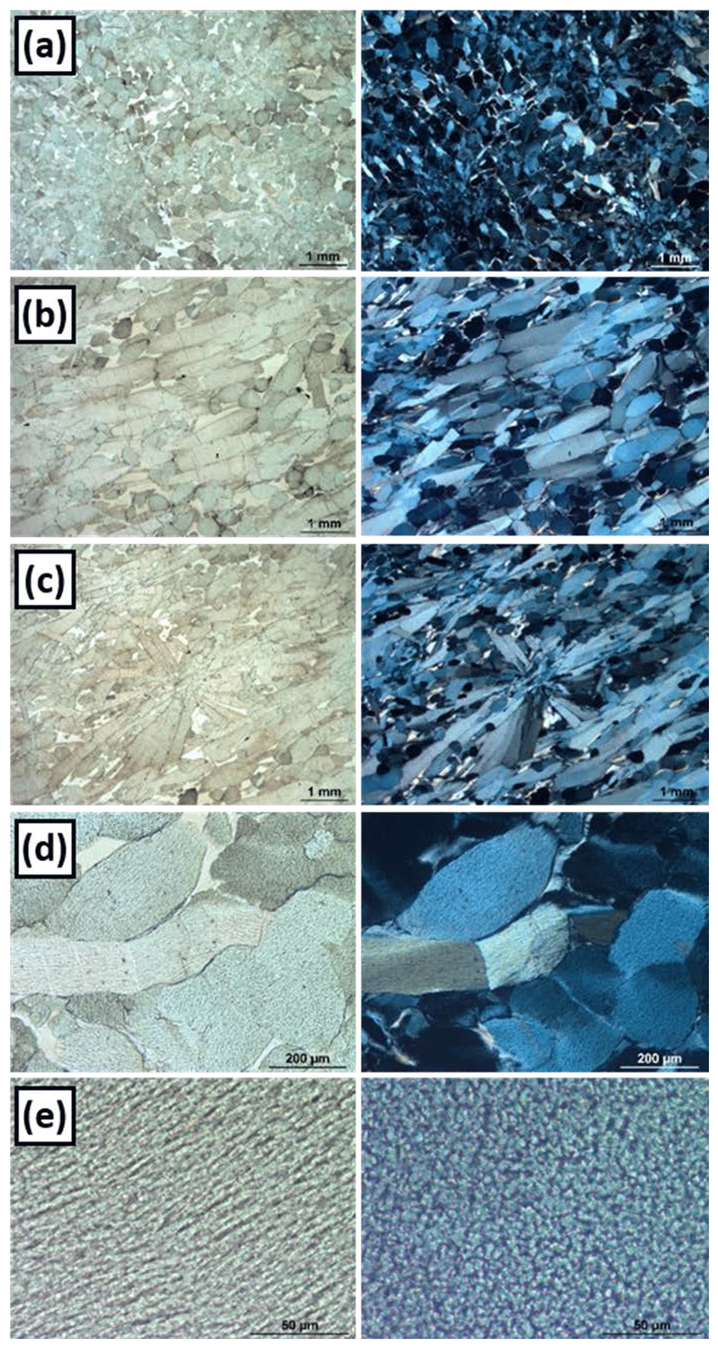
Figure 1Photomicrographs of the lizardite vein. (a) Perpendicular to mineral lineation. The colourless interstitial matrix (left) consists of chrysotile and polygonal serpentine. Left: plane-polarized light (PPL). Right: crossed polarizers (XPs). Thin section MM91A. (b) Parallel to mineral lineation. Left: PPL; right: XPs. Thin section MM91B. (c) Radial aggregate of prismatic lizardite, grown in a vein with main foliation (ENE-WSW) still evident. Left: PPL; right: XPs. Thin section MM91B. (d) Lizardite prism with evident post-crystalline deformation features. Left: PPL; right: XPs. Thin section MM91B. (e) High-magnification photomicrographs of lizardite crystals, cut parallel (left) and perpendicular (right) to prism elongation. PPL, thin section MM91A.
The most interesting veins are those containing euhedral prismatic lizardite. These veins, which are a few metres long and a few decimetres thick, mostly consist of prismatic lizardite-1T embedded in a fibrous matrix of chrysotile and minor polygonal serpentine, whose amount varies from sample to sample. In the field, prismatic lizardite defines an evident mineral lineation, which locally appears slightly deformed. Following the interpretation of O'Hanley (1991), this assemblage was due to dynamic serpentinite recrystallization assisted by deformation and shearing along active joints.
From one of the samples studied by Viti and Mellini (1997), two thin sections were obtained, parallel (MM91A) and perpendicular (MM91B) to the elongation of lizardite crystals. Perpendicularly to lineation, most of the prismatic lizardite crystals show a stumpy or roundish shape and a greenish colour (Fig. 1a). Conversely, parallel to mineral lineation, most of the lizardite crystals have a long prismatic habit (Fig. 1b) and evident pleochroism (Fig. 1b, left). However, in spite of the clear mineral lineation defined by the preferred orientation of lizardite prisms, radial aggregates of prismatic crystals also occur in both sections (Fig. 1c). This indicates that some lizardite crystals locally grew in a more complex way, with a three-dimensional radial arrangement, possibly indicative of static conditions. In summary, lizardite has a prismatic habit, with crystals elongated along the crystallographic c axis (Fig. 1a and b). The lizardite size ranges from 1 to 3 mm in length by 0.3 mm across, with an aspect ratio of up to 10. Most crystals show a spaced (001) cleavage system perpendicular to prism elongation (Fig. 1b). Lizardite is optically uniaxial with a negative sign and low birefringence (ca. 0.008). Prismatic crystals show parallel extinction and are pleochroic with ε being yellowish (parallel to crystal elongation, i.e. parallel to [001]) and ω being light greenish (perpendicular to crystal elongation). The elongation sign is negative (length fast).
The lizardite crystals are embedded in a light beige to colourless interstitial matrix of fibrous serpentine (Fig. 1a, left, and 1b, left), recognized to consist of chrysotile and minor polygonal serpentine on the grounds of TEM observations (Viti and Mellini, 1997). The amount of interstitial fibrous serpentine varies from place to place and from sample to sample. Post-crystalline deformation is evident, tested by local bending and stretching of lizardite crystals and kinking of the interstitial chrysotile (Fig. 1d).

Figure 2Raman results. (a) Enlarged portion of a lizardite crystal cut ⊥ to ε (cf. Fig. 1e, right) with the trace of the line scan, with 19 point analyses taken at 0.5 µm steps. Sample MM91A. (b) Cumulative diagram of the 19 spectra obtained at 0.5 µm steps along the blue line in (a). The gathering of the blue spectra, which correspond to the lighter portions, indicates that this is the prevailing phase. (c) High-wavenumber spectra for the darker portion in (a). Experimental pattern (red) and fitted peaks (black). (d) High-wavenumber spectra for the lighter portion in (a). Experimental pattern (red) and fitted peaks (black).
Observed under the polarizing microscope at high magnification, lizardite reveals an internal microstructure, with “fibrous” (Fig. 1e, left) or “spongy/cribriform” appearance (Fig. 1e, right), for crystals seen parallel or perpendicularly to prism elongation, respectively. This microstructure is mostly evident in sections perpendicular to the lizardite elongation, where the spongy appearance derives from lighter domains (5–10 µm wide), surrounded by darker micrometric rims (Fig. 2a). The microstructure is due to a fine intermixture of phases with different “reliefs”. Under crossed polarizers, the interference figures of sections cut perpendicularly to the lizardite prism elongation give a centred black cross, typical of negative uniaxial crystals cut ⊥ to ε. Furthermore, the lack in the interference figure of the isochromes indicates a low birefringence mineral. Both features are compatible with lizardite-1T, which is the volumetrically prevailing phase. The domain extensions were evaluated processing the microscopic images with the MultiSpec program (Purdue Research Foundation); first, the three available bands (red, green and blue) were imported and, afterwards, 11 areas were selected to characterize the two classes by means of the Gaussian maximum likelihood function. This evaluation, performed on several sections, indicates that lizardite (87 %) prevails over “voids” (13 %). As the accompanying TEM observations show that intermixed chrysotile (Ctl) and polygonal serpentine (PS) fibres do not fill the entire void volume, we suppose a still greater lizardite content, possibly on the order of 90 % lizardite.
Attempts to discriminate the chemical compositions by SEM–energy dispersive spectroscopy (EDS) were unsuccessful, as similar values were obtained everywhere. This differs from what was observed by Viti and Mellini (1997) when comparing lizardite and the intercrystalline, interstitial chrysotile and polygonal serpentine, which develop at a definitely larger scale. Therefore, we tried further characterization by μ-Raman spectroscopy, whose laser beam with a 100× objective has a spatial resolution of 1 µm, comparable with the average size of the two intermixed phases (Fig. 2).
4.1 Operating conditions
Raman spectra were obtained at the Department of Earth Sciences, University of Turin, using a Horiba Jobin Yvon HR800 LabRAM instrument equipped with a Nd:YAG green laser (532 nm) in N–S-polarized mode, delivering 8 mW to the sample; an Olympus BX40 optical microscope; and a CCD detector cooled to −70 ∘C by the Peltier effect. The analytical conditions were a 200 µm confocal hole, 100× objective (1 µm lateral spatial resolution), and 1 cm−1 spectral resolution with 600 grooves mm−1 gratings. Measurements were made on polished thin sections. The spectrometer was calibrated with a silicon standard (520.7 cm−1). Acquisition time was 10 s with 10 accumulations per spot. Spectra were processed using the acquisition LabSpec 5 software.
Band component analysis was undertaken using the Horiba Jobin Yvon LabSpec 5 software package, which affords selection of the fitting function, as well as of variable parameters. Band fitting was performed using a Voigt cross-product function with the minimum number of bands used for the fitting process. Fitting proceeded until the obtainment of reproducible results with root mean square error r2 correlations greater than 0.995.
4.2 μ-Raman results
The possible overlap of intermixed phases during μ-Raman acquisition was reduced choosing the thin section perpendicular to crystal elongation, i.e. ⊥-to-ε optic axis (Fig. 1e, right), being the one with better phase resolution. Furthermore, as shown by Compagnoni et al. (2021), this orientation does not present anisotropic Raman effects. Therefore, a simpler interpretation may be expected. Background was removed from the spectra before the best-fitting procedure, by means of the baseline option (type, polynomial; degree, 2) of the LabSpec 5 software.
At first, we performed line scans over the whole lizardite microstructure, focusing on the high-wavenumber region, which is the most sensitive to O–H bonds (Fig. 2). The line scan consists of 19 points analysed at steps of 0.5 µm (Fig. 2a). Two extreme spectra are evident in the cumulative results (Fig. 2b), thus confirming that at least two phases concur with the optically resolved microstructure. The main spectrum is sharp and consists of two peaks at 3686 and 3705 cm−1; it occurs in 16 of 19 spots. The other one appears as a poorly resolved wide band, confined between the two previous sharp peaks. Pairing with Fig. 2a shows that the most frequent spectrum originates from the lighter domains, while the less frequent one corresponds to the darker rims.
Two adjacent points, representative of the spongy microstructure (Fig. 1e, right), were selected for further μ-Raman acquisition. The resulting spectra (Fig. 2c and d) are in agreement with Fig. 2b and confirm the association of different phases; in particular, the red bands of Fig. 2c and d originate from the lighter and the darker zone (Figs. 1e and 2a), respectively, fitting results in black.
As far as phase identification is concerned, we make reference again to Compagnoni et al. (2021). In the case of lighter domains, the two sharp peaks at 3686 and 3705 cm−1 well match the values of 3688 and 3706 cm−1 previously reported for the ω–ω section of lizardite. By the way, we remark that such a straightforward identification would be hampered if neglecting the orientation issue; in fact, the same lizardite, when examined in an ε–ω section, would produce two peaks at 3678 and 3707 cm−1.
Conversely, the dark domains are characterized by a Raman band at 3699 cm−1. This value is typical of chrysotile (in any orientation), but fitted bands close to 3699 cm−1 may be present also, as minor peaks, in polygonal serpentine.
5.1 Experimental
TEM samples were prepared at the Department of Physical Sciences, Earth and Environment of the University of Siena by ion milling a double-polished thin section with a Gatan PIPS. Lizardite grains oriented with the c axis circa parallel to the microscope optical axis were selected under the polarizing microscope. In detail, a Cu ring 3 mm wide with an aperture of 1500 µm was placed around a cluster of three lizardite grains, approximately 3–400 µm in diameter. A hole was produced at the centre of the aperture and care was taken to direct the TEM observations within the crystals far away from the rims, which were possibly occupied by intercrystalline chrysotile veins (Viti and Mellini, 1997).
TEM observations were performed with a JEOL JEM-2100Plus instrument at the Microscopy Platform of the University of Milano-Bicocca. The instrument is equipped with a 9 MP Gatan Rio CMOS camera for image acquisition and an Oxford energy dispersive spectroscopy (EDS) system for chemical analysis.
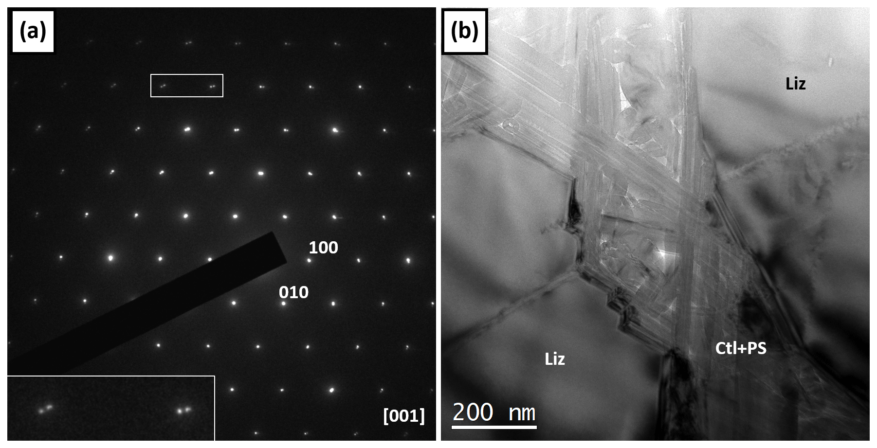
Figure 3TEM results. (a) SAED pattern of lizardite seen along [001]. Note spot splitting in the upper left part of the image (and enlarged inset), suggesting slight misorientation among lizardite domains; (b) lizardite grains (Liz) with intermixed chrysotile (Ctl) and polygonal serpentine (PS) veins. Fibres show preferred orientation, lying parallel to the lizardite rims and mutually rotated by 120∘. Zigzag stepped lizardite rims visible everywhere. Further Ctl and PS fibres lying parallel to [001] Liz are visible at the centre and in the upper central part of the image.

Figure 4TEM results. (a) BF image of [001] lizardite, intermixed with abundant chrysotile. Moiré fringes, i.e. interference features due to superposition of flat periodic objects (possibly serpentine grains) in different orientations, are visible in the upper left. The fast Fourier transform (FFT) of the central portion (inset) shows “star” intensity distribution suggesting preferred fibre orientation, rotated about n60∘ (equivalent to 120∘) relative to each other. (b) SAED pattern of lizardite plus chrysotile; the chrysotile diffractions (spots and streaks), parallel to the lizardite lattice, indicate crystallographic control on the chrysotile orientation. Some basal lizardite reflections (left-pointing arrows) and some 00l chrysotile reflections (right-pointing arrows) are indicated, and some are labelled.
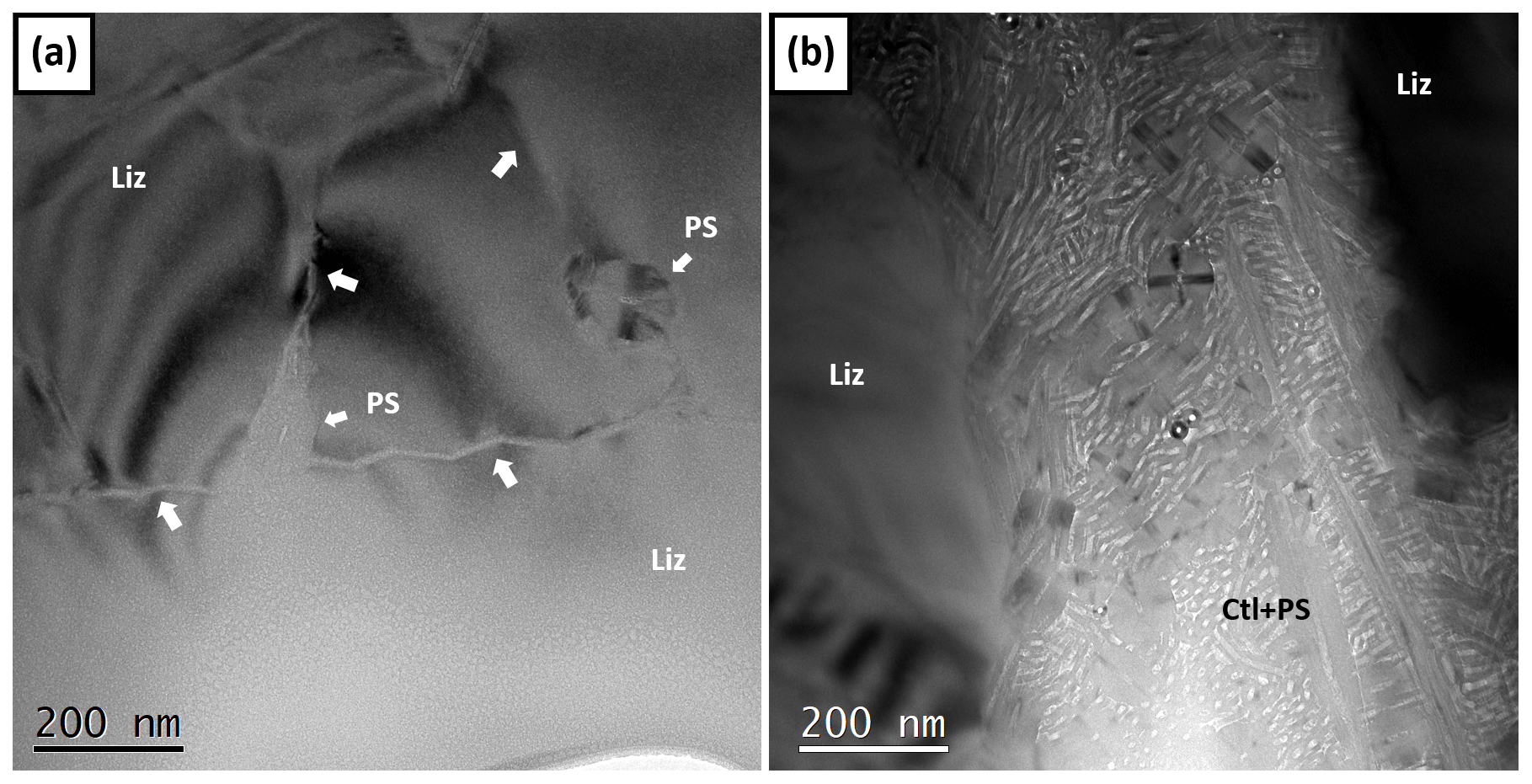
Figure 5TEM results. (a) Insulated polygonal serpentine fibres (arrows) within [001] lizardite. The fibre sites are interconnected by narrow zigzag contours (large arrows). (b) Large void in lizardite filled by chrysotile and polygonal serpentine fibres. Most fibres are parallel to the [001] observation direction.
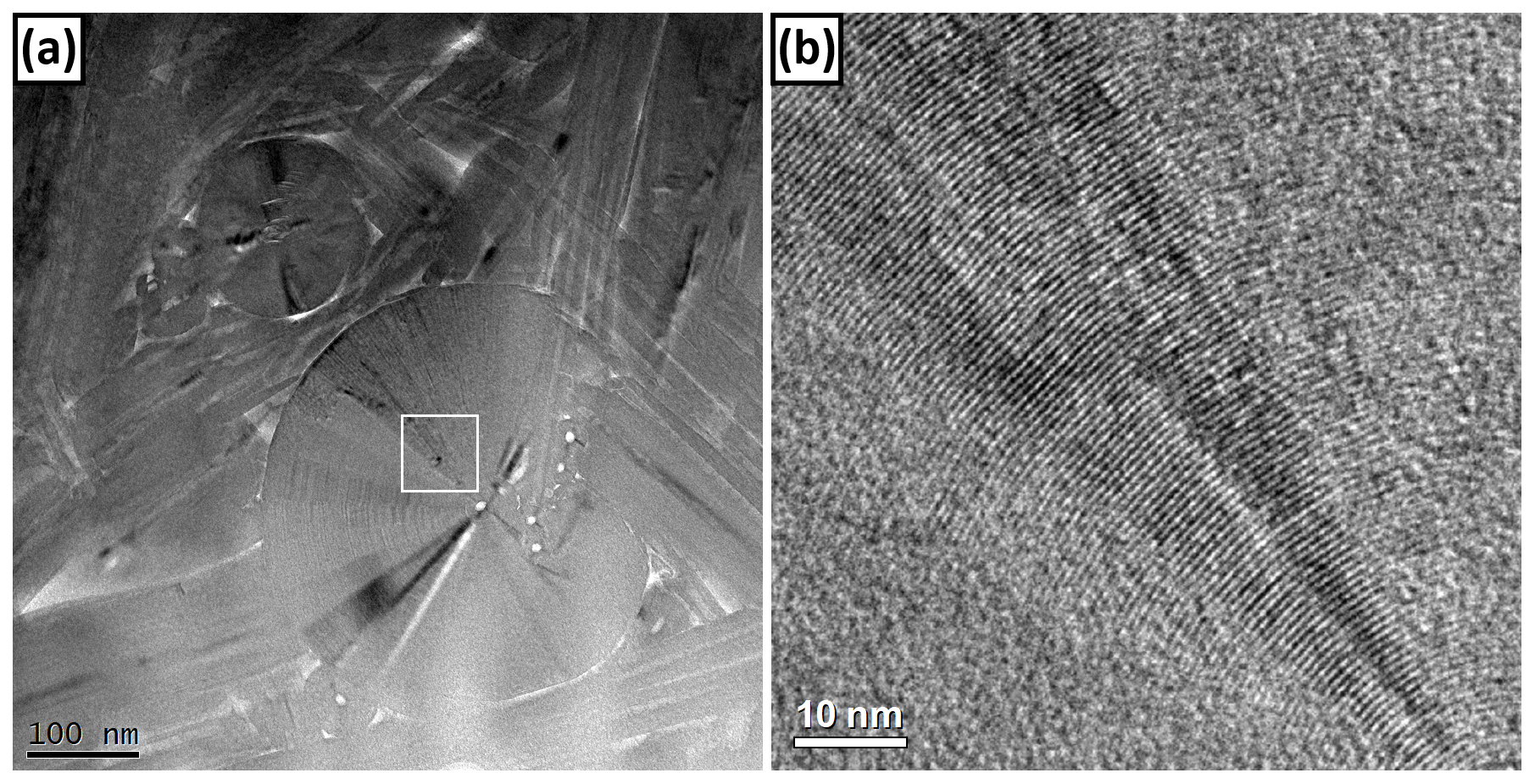
Figure 6TEM results. (a) Polygonal serpentine within lizardite and (b) high-resolution image of the polygonal sectors. The abrupt deflection of the flat lizardite-like lattice planes is evident.
5.2 TEM results
Lizardite is definitely crystalline, as tested by the sharp selected area electron diffraction (SAED) patterns (Fig. 3a) obtained over micrometric regions. Notwithstanding, the lizardite crystals host voids, usually with submicrometric thickness. Chrysotile and polygonal fibres occur within these voids, forming thin veins (Figs. 3b and 4a); as chrysotile starts to polygonalize at about 30 nm, many of the observed fibres are actually tiny polygonal serpentine fibres in the initial polygonalization stage. Across the veins, the lizardite crystals exhibit stepped rims, with 120∘ zigzag contours (Figs. 3b and 4a). Within the veins, chrysotile and polygonal serpentine form a network of fibres mutually rotated by 120∘, lying parallel to the stepped lizardite rims. This network may leave voids, which are occupied by a second chrysotile and polygonal serpentine generation, with fibres now oriented perpendicularly to the 120∘ fibre network.
In some cases, (e.g. Figs. 3b and 4a), the lizardite crystal recalls a tessellation of hexagonal plates, suggesting the presence of a well-matching domain structure. SAED patterns obtained on lizardite and intergrown chrysotile show streaks along the [100]* and [010]* (and symmetry-related) lizardite directions (Fig. 4b), suggesting chrysotile fibres elongated parallel to the {100} and {010} lizardite facets. These facets behave as surfaces where the chrysotile fibres nucleate, under tight crystallographic control. The above observation also implies that the x axis is the rolling axis of chrysotile, consistent with the recognized chrysotile-2Mc1, chrysotile-2Orc1 and chrysotile-1Mc1 structures (Wicks and Whittaker, 1975). The rare, sporadic occurrence of Moiré interference patterns (Fig. 4a) testifies to the overlap of lizardite plates and Ctl/PS regions.
Further chrysotile and polygonal serpentine fibres are shown in Fig. 4. Most of the fibres lie horizontally in the observation plane, regularly rotated by 120∘, as also testified to by the fast Fourier transform (FFT) (inset Fig. 4). Here also, a few chrysotile and polygonal serpentine fibres run perpendicularly to the previous ones.
Figure 5a shows another evident 120∘ thin zigzag vein, running left to right. Less evident are two further veins (approximately 60∘ from the previous one) that run bottom to top. Both host a vertical polygonal serpentine fibre, 80–100 nm in diameter. More polygonal serpentine fibres may be seen in Fig. 5b, together with several chrysotile fibres; the two kinds of fibres lie either vertically or horizontally.
Figure 6a depicts one of the largest polygonal fibres observed. This fibre is approximately 400 nm in diameter; it consists of 30 sectors. Moving from the centre to the rim (inset of Fig. 6a, expanded as Fig. 6b), details of polygonalization become evident.
The optical examination of the lizardite thin sections has evidenced an intracrystalline microstructure within the prismatic crystals. The microstructure appears as an intermixture of phases with different reliefs. Basal sections of the most abundant phase produce sharp interference figures, typical of optically negative uniaxial crystals, cut perpendicularly to the optic axis. Obviously, these are the properties expected for lizardite. The minor phase forms micrometric regions with chemical composition very close to lizardite. Although hypothetically distinguishable from lizardite by careful SEM-EDS analysis, the close chemical compositions and possible three-dimensional mutual contamination effects precluded this possibility.
Owing to the size of the intracrystalline microstructure, contamination effects may also be present in the μ-Raman spectra, having a lateral spatial resolution of 1 µm. Sections cut perpendicularly to the crystal elongation (i.e. ⊥-to-ε optic axis) show the two phases as separate lighter and darker regions (Fig. 2). Whereas the major phase is univocally determined as lizardite on the basis of μ-Raman data, the darker domains produce poorly resolved μ-Raman spectra, interpreted as the sum of lizardite and chrysotile (with possible polygonal serpentine too).
TEM observations confirm the presence of chrysotile (plus polygonal serpentine), with further details that reveal a still more complex microstructure. Basically, the optically darker domains consist of veins hosting a network of chrysotile and polygonal serpentine fibres, oriented in three directions rotated by n60∘ relative to each other. A further generation of chrysotile and polygonal serpentine occurs as fibres grown perpendicularly to the previous ones (and therefore parallel to the optic axis). Somewhere, the second-generation polygonal serpentine appears to have grown at the expense of the first-generation chrysotile. When particularly developed, it is recognized as 30-sector polygonal serpentine (Fig. 6a).
Chrysotile and lizardite show tight crystallographic relationships, such as those evident from Fig. 4, suggesting that the two minerals grew in a concerted way. In other words, the lizardite crystals grew up with a skeletal habit and the chrysotile fibres filled the voids, growing epitactically on the lizardite crystals. The possible comparison of these fibres with the lizardite scrolls observed by Wicks and Chatfield (2005) seems unlikely, due to the important differences existing between the two samples. In particular, whereas lizardite scrolls seem triggered by an elastic stress recovery acting on very thin TO-layer packets of lizardite, in the Monte Fico lizardite {100} and {010} facets act as nucleation sites for chrysotile.
In general, skeletal growth of minerals is promoted by fast crystal growth, made possible in a fluid-rich environment. Such conditions occurred in the Monte Fico veins, as suggested by the huge size of lizardite prisms. These conditions would be common for the formation of the present intracrystalline lizardite–chrysotile–polygonal serpentine microstructure and for the formation of the larger-scale intercrystalline lizardite–chrysotile–polygonal serpentine microstructure previously described by Viti and Mellini (1997).
Although definitely pervasive, the minor phases (chrysotile and polygonal serpentine) characterizing the intracrystalline microstructure (probably consisting of more than 90 % lizardite) apparently behave as background noise, unable to induce any evident features in the different characterizations undergone by the Monte Fico lizardite.
No data sets were used in this article.
RCom and RCos planned the study, collected optical and Raman data, interpreted the results, and wrote the paper. GC made TEM observations and interpretations and contributed to manuscript writing and revision. SB assisted in optical image acquisition. Last but not least MM took advantage of the frequent coffee breaks to shape the conceptual framework of the paper and mould the writing of the final manuscript.
The authors declare that they have no conflict of interest.
Publisher's note: Copernicus Publications remains neutral with regard to jurisdictional claims in published maps and institutional affiliations.
The μ-Raman data were obtained with the equipment acquired by the “Giovanni Scansetti” Interdepartmental Centre for Studies on Asbestos and Other Toxic Particulates, The University of Turin, with a grant from Compagnia di San Paolo, Turin.
The manuscript was improved through the careful reviews by Etienne Balan, Bertrand Devouard and the anonymous referee.
This work is an outcome of the project DEAR – Deattivazione Efficiente dell'Amianto e Riutilizzo funded by the Ministero della Transizione Ecologica (MiTE) within the remit of Strategia Nazionale per lo Sviluppo Sostenibile (SNSvS).
This work is dedicated to the memory of Volkmar Trommsdorff, a good friend and wonderful mentor who linked field geology, microscopy and theoretical petrography.
This paper was edited by Etienne Balan and reviewed by Bertrand Devouard and one anonymous referee.
Amiguet, E., Reynard, B., Caracas, R., Van de Moortele, B., and Wang, Y.: Creep of phyllosilicates at the onset of plate tectonics, Earth Planet. Sc. Lett., 345, 142–150, 2012.
Auzende, A. L., Daniel, I., Reynard, B., Lemaire, C., and Guyot, F.: High-pressure behaviour of serpentine minerals: A Raman spectroscopic study, Phys. Chem. Miner., 31, 269–277, 2004.
Compagnoni, R., Cossio, R., and Mellini, M.: Raman anisotropy in serpentine minerals, with a caveat on identification, J. Raman Spectr., 52, 1334–1345, https://doi.org/10.1002/jrs.6128, 2021.
Fuchs, Y., Linares, J., and Mellini, M.: Mössbauer and infrared spectrometry of lizardite-1T from Monte Fico, Elba. Phys. Chem. Miner., 26, 111–115, 1998.
Gailhanou, H., Blanc, P., Mikaelian, G., Rogez, J., and Kawaji, H.: Thermodynamic properties of lizardite, determined by calorimetry. International Symposium on Solubility Phenomena and Related Equilibrium Processes (ISSP), Tours, France, HAL Id: hal-01720566, available at: https://hal-brgm.archives-ouvertes.fr/hal-01720566 (last access: 26 July 2021), 2018.
Gregorkiewitz, M., Lebech, B., Mellini, M., and Viti, C.: Hydrogen positions and thermal expansion in lizardite-1T from Elba: a low-temperature study using Rietveld refinement of neutron diffraction data, Am. Mineral., 81, 1111–1116, 1996.
Hilairet, N., Daniel, I., and Reynard, B.: P–V Equations of State and the relative stabilities of serpentine varieties, Phys. Chem Miner., 33, 629–637, 2006.
Hirose, T., Bystricky, M., Kunze, K., and Stünitz, H.: Semi-brittle flow during dehydration of lizardite–chrysotile serpentinite deformed in torsion: Implications for the rheology of oceanic lithosphere, Earth Planet. Sc. Lett., 249, 484–493, 2006.
Lacinska, A. M., Styles, M. T., Bateman, K., Wagner, D., Hall, M. R., Gowing, C., and Brown, P. D.: Acid-dissolution of antigorite, chrysotile and lizardite for ex situ carbon capture and storage by mineralisation, Chem. Geol., 437, 153–169, 2016.
Mellini, M. and Viti, C.: Crystal structure of lizardite-1T from Elba, Italy, Am. Mineral., 79, 1194–1198, 1994.
O'Hanley, D. S.: Fault-related phenomena associated with hydration and serpentine recrystallization during serpentinization, Can. Mineral., 29, 21–35, 1991.
Rinaudo, C., Gastaldi, D., and Belluso, E.: Characterization of chrysotile, antigorite and lizardite by FT-Raman spectroscopy, Can. Mineral., 41, 883–890, 2003.
Trittschack, R., Grobéty, B., and Koch-Müller, M.: In situ high-temperature Raman and FTIR spectroscopy of the phase transformation of lizardite, Am. Mineral., 97, 1965–1976, 2012.
Viti, C.: Serpentine minerals discrimination by thermal analysis, Am. Mineral., 95, 631–638, 2010.
Viti, C. and Hirose, T.: Dehydration reactions and micro-nanostructures in experimentally-deformed serpentinites, Contr. Mineral. Petrol., 157, 327–338, 2009.
Viti, C. and Mellini, M.: Vein antigorites from Elba Island, ltaly, Eur. J. Mineral., 8, 423–434, 1996.
Viti, C. and Mellini, M.: Contrasting compositions in coexisting chrysotile and lizardite in veins from Elba, Italy, Eur. J. Mineral., 9, 585–596, 1997.
Viti, C. and Mellini, M.: Mesh textures and bastites in the Elba retrograde serpentinites, Eur. J. Mineral., 10, 1341–1359, 1998.
Wicks, F. J. and Chatfield, E. J.: Scrolling of thin crystals of lizardite: an expression of internal stress, Can. Mineral., 43, 199–2004, 2005.
Wicks, F. J. and Whittaker, E. J. W.: A reappraisal of the structures of the serpentine minerals, Can. Mineral., 13, 227–243, 1975.
- Abstract
- Introduction
- Field occurrence and petrography
- The lizardite intracrystalline microstructure (optical)
- μ-Raman spectroscopy
- The lizardite intracrystalline microstructure (TEM)
- Discussion and conclusions
- Data availability
- Author contributions
- Competing interests
- Disclaimer
- Acknowledgements
- Review statement
- References
spongymicrostructure. TEM observations confirmed that the Lz hosts voids, filled with chrysotile and polygonal serpentine; their mutual relationships indicate that Lz grew up with a skeletal habit and fibres epitactically.
- Abstract
- Introduction
- Field occurrence and petrography
- The lizardite intracrystalline microstructure (optical)
- μ-Raman spectroscopy
- The lizardite intracrystalline microstructure (TEM)
- Discussion and conclusions
- Data availability
- Author contributions
- Competing interests
- Disclaimer
- Acknowledgements
- Review statement
- References